Table of Contents
Advertisement
Advertisement
Table of Contents

Related Manuals for Asus A68HM Series


Summary of Contents for Asus A68HM Series
- Page 1 A68HM Series E9808_A68HM Series_Manual.indb 1 2014/10/16 10:08:57...
- Page 2 Product warranty or service will not be extended if: (1) the product is repaired, modified or altered, unless such repair, modification of alteration is authorized in writing by ASUS; or (2) the serial number of the product is defaced or missing.
-
Page 3: Table Of Contents
Contents Safety information ...................... iv About this guide ......................iv Package contents ....................... vi A68HM Series specifications summary ..............vi Product introduction Before you proceed ..................1-1 Motherboard overview ................. 1-1 Accelerated Processing Unit (APU) ............1-3 System memory .................... 1-6 Expansion slots .................... -
Page 4: Safety Information
Safety information Electrical safety • To prevent electrical shock hazard, disconnect the power cable from the electrical outlet before relocating the system. • When adding or removing devices to or from the system, ensure that the power cables for the devices are unplugged before the signal cables are connected. If possible, disconnect all power cables from the existing system before you add a device. -
Page 5: Conventions Used In This Guide
Refer to the following sources for additional information and for product and software updates. ASUS websites The ASUS website provides updated information on ASUS hardware and software products. Refer to the ASUS contact information. Optional documentation Your product package may include optional documentation, such as warranty flyers, that may have been added by your dealer. -
Page 6: Package Contents
Dual-channel memory architecture Supports AMD Memory Profile (AMP) memory • Hyper DIMM support is subject to the physical characteristics of individual CPUs. • The maximum 32GB memory capacity can be supported with 16GB or above DIMMs. ASUS will update the memory QVL once the DIMMs are available in the market. • Refer to www.asus.com for the latest Memory QVL (Qualified Vendors List). • When you install a total memory of 4GB capacity or more, Windows ®... - Page 7 - ASUS Enhanced DRAM Overcurrent Protection - Short circuit damage prevention - ASUS ESD Guards - Enhanced ESD protection - ASUS High Quality 5K-Hour Solid Capacitors - 2.5x long lifespan with excellent durability - ASUS Stainless Steel Back I/O - 3x more durable corrosion-resistant...
- Page 8 A68HM Series specifications summary 1 x PS/2 mouse port (green) Back Panel I/O ports 1 x PS/2 keyboard port (purple) 1 x DVI-D port 1 x D-Sub output port 1 x LAN (RJ-45) port 2 x USB 2.0/1.1 ports 2 x USB 3.0 ports 7.1-channel audio I/O ports (3-jack)
-
Page 9: Product Introduction
The edge with external ports goes to the rear part of the chassis as indicated in the image below. 1.2.2 Screw holes Place six screws into the holes indicated by circles to secure the motherboard to the chassis. Do not overtighten the screws! Doing so can damage the motherboard. ASUS A68HM Series E9808_A68HM Series_Manual.indb 1 2014/10/16 10:08:58... -
Page 10: Motherboard Layout
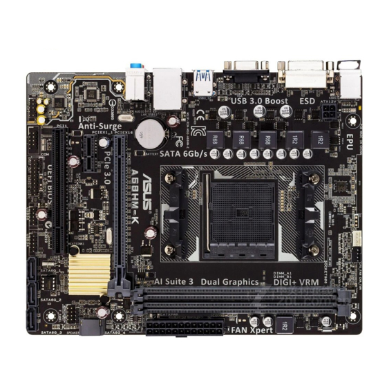
Place this side towards the rear of the chassis A68HM-E The layout illustrations in this user manual are for A68HM-E only. 1.2.3 Motherboard layout 18.0cm(7.0in) KBMS CPU_FAN CHA_FAN DIGI +VRM ATX12V USB1112 LAN_USB12 BATTERY AUDIO A68HM-E 8111 PCIEX16 Super ® PCIEX1_1 A68H SPEAKER F_PANEL PCI1 64Mb BIOS SPDIF_OUT USB56 USB34 SATA6G_1 SATA6G_2 SATA6G_3... -
Page 11: Accelerated Processing Unit (Apu)
1-18 9. Clear RTC RAM (2-pin CLRTC) 1-10 10. TPM connector (20-1 pin TPM) 1-13 11. Digital audio connector (4-1 pin SPDIF_OUT) 1-15 12. Serial port connector (10-1 pin COM) 1-18 13. Front panel audio connector (10-1 pin AAFP) 1-17 Accelerated Processing Unit (APU) This motherboard comes with an FM2+ socket designed for AMD A-series / Athlon™ Series ® graphics. A68HM-E A68HM-E CPU socket FM2+ Ensure that you use an APU designed for the FM2+ socket. The APU fits in only one correct orientation. DO NOT force the APU into the socket to prevent bending the pins and damaging the APU! ASUS A68HM Series E9808_A68HM Series_Manual.indb 3 2014/10/16 10:08:58... -
Page 12: Installing The Apu
1.3.1 Installing the APU 1.3.2 APU heatsink and fan assembly installation Apply the Thermal Interface Material to the APU heatsink and APU before you install the heatsink and fan if necessary. Chapter 1: Product introduction E9808_A68HM Series_Manual.indb 4 2014/10/16 10:09:00... - Page 13 To install the APU heatsink and fan assembly To uninstall the APU heatsink and fan assembly ASUS A68HM Series E9808_A68HM Series_Manual.indb 5 2014/10/16 10:09:01...
-
Page 14: System Memory
System memory 1.4.1 Overview The motherboard comes with two Double Data Rate 3 (DDR3) Dual Inline Memory Modules (DIMM) sockets. A DDR3 module has the same physical dimensions as a DDR2 DIMM but is notched differently to prevent installation on a DDR2 DIMM socket. DDR3 modules are developed for better performance with less power consumption. The figure illustrates the location of the DDR3 DIMM sockets: Channel Sockets Channel A DIMM_A1 Channel B DIMM_B1 A68HM-E A68HM-E 240-pin DDR3 DIMM sockets Chapter 1: Product introduction E9808_A68HM Series_Manual.indb 6 2014/10/16 10:09:02... -
Page 15: Memory Configurations
® or more memory on the motherboard, the actual usable memory for the OS can be about 3GB or less. For effective use of memory, we recommend that you do any of the following: Install a maximum of 3GB system memory if you are using a 32-bit Windows® Use a 64-bit Windows OS if you want to install 4GB or more memory on the ® motherboard. • This motherboard does not support DIMMs made up of 512Mb (64MB) chips or less. • The maximum 32GB memory capacity can be supported with 16GB or above DIMMs. ASUS will update the memory QVL once the DIMMs are available in the market. • The default memory operation frequency is dependent on its Serial Presence Detect (SPD), which is the standard way of accessing information from a memory module. Under the default state, some memory modules for overclocking may operate at a lower frequency than the vendor-marked value. To operate at the vendor-marked or at a higher frequency, refer to section 2.5 Ai Tweaker menu for manual memory frequency adjustment. • For system stability, use a more efficient memory cooling system to support a full memory load (2 DIMMs) or overclocking condition. • Refer to www.asus.com for the latest Memory QVL (Qualified Vendors List). ASUS A68HM Series E9808_A68HM Series_Manual.indb 7 2014/10/16 10:09:02... -
Page 16: Installing A Dimm
1.4.3 Installing a DIMM To remove a DIMM Chapter 1: Product introduction E9808_A68HM Series_Manual.indb 8 2014/10/16 10:09:02... -
Page 17: Expansion Slots
Remove the system unit cover (if your motherboard is already installed in a chassis). Remove the bracket opposite the slot that you intend to use. Keep the screw for later use. Align the card connector with the slot and press firmly until the card is completely seated on the slot. Secure the card to the chassis with the screw you removed earlier. Replace the system cover. 1.5.2 Configuring an expansion card After installing the expansion card, configure it by adjusting the software settings. Turn on the system and change the necessary BIOS settings, if any. See Chapter 2 for information on BIOS setup. Assign an IRQ to the card. Install the software drivers for the expansion card. When using PCI cards on shared slots, ensure that the drivers support “Share IRQ” or that the cards do not need IRQ assignments. Otherwise, conflicts will arise between the two PCI groups, making the system unstable and the card inoperable. 1.5.3 PCI slot The PCI slot supports cards such as a LAN card, SCSI card, USB card, and other cards that comply with PCI specifications. ASUS A68HM Series E9808_A68HM Series_Manual.indb 9 2014/10/16 10:09:02... -
Page 18: Headers
1.5.4 PCI Express x1 slot This motherboard supports PCI Express 2.0 x1 network cards, SCSI cards, and other cards that comply with the PCI Express specifications. 1.5.5 PCI Express x16 slot This motherboard supports one PCI Express 3.0/2.0 x16 graphics cards that comply with the PCI Express specifications. IRQ assignments for this motherboard PCIEx16_1 – – shared – – – – – PCIEx1_1 shared – – – – – – – PCI1 slot – – –... -
Page 19: Connectors
LAN port LED indications ACT/LINK SPEED Activity/Link LED Speed LED Status Description Status Description No link 10Mbps connection Orange Linked ORANGE 100Mbps connection LAN port Orange (Blinking) Data activity GREEN 1Gbps connection Orange (Blinking Ready to wake up then steady) from S5 mode ASUS A68HM Series 1-11 E9808_A68HM Series_Manual.indb 11 2014/10/16 10:09:03... - Page 20 Line In port (light blue). This port connects to the tape, CD, DVD player, or other audio sources. Line Out port (lime). This port connects to a headphone or a speaker. In the 4.1, 5.1, and 7.1-channel configurations, the function of this port becomes Front Speaker Out. Microphone port (pink). This port connects to a microphone. Refer to the audio configuration table below for the function of the audio ports in 2.1, 4.1, 5.1, or 7.1-channel configuration. Audio 2.1, 4.1, 5.1, or 7.1-channel configuration Headset Port 2.1- 4.1-channel 5.1-channel 7.1-channel channel Light Blue (Rear panel) Line In Rear Speaker Out Rear Speaker Out Rear Speaker Out Lime (Rear panel)
-
Page 21: Internal Connectors
A68HM-E Fan connectors DO NOT forget to connect the fan cables to the fan connectors. Insufficient air flow inside the system may damage the motherboard components. These are not jumpers! DO NOT place jumper caps on the fan connectors. • The CPU_FAN connector supports a CPU fan of maximum 2A (24 W) fan power. • The CPU_FAN and CHA_FAN connectors support the ASUS Fan Xpert feature. TPM connector (20-1 pin TPM) This connector supports a Trusted Platform Module (TPM) system, which can securely store keys, digital certificates, passwords, and data. A TPM system also helps enhance network security, protects digital identities, and ensures platform integrity. PIN 1 A68HM-E A68HM-E TPM connector The TPM module is purchased separately. ASUS A68HM Series 1-13 E9808_A68HM Series_Manual.indb 13 2014/10/16 10:09:04... -
Page 22: Atx Power Connectors
A68HM-E ATX power connectors • We recommend that you use an ATX 12V Specification 2.0-compliant power supply unit (PSU) with a minimum of 300W power rating. This PSU type has 24-pin and 4-pin power plugs. • If you intend to use a PSU with 20-pin and 4-pin power plugs, ensure that the 20-pin power plug can provide at least 15 A on +12V and that the PSU has a minimum power rating of 300W. The system may become unstable or may not boot up if the power is inadequate. • DO NOT forget to connect the 4-pin ATX +12V power plug. Otherwise, the system will not boot up. • We recommend that you use a PSU with higher power output when configuring a system with more power-consuming devices or when you intend to install additional devices. The system may become unstable or may not boot up if the power is inadequate. • If you are uncertain about the minimum power supply requirement for your system, refer to the Recommended Power Supply Wattage Calculator at http://support.asus. com/PowerSupplyCalculator/PSCalculator.aspx?SLanguage=en-us for details. 1-14 Chapter 1: Product introduction E9808_A68HM Series_Manual.indb 14 2014/10/16 10:09:04... - Page 23 A68HM-E SATA 6.0Gb/s connectors • These connectors are set to AHCI mode by default. If you intend to create a Serial ATA RAID set using these connectors, set the type of the SATA connectors in the BIOS to [RAID]. • You must install Windows XP Service Pack 3 or later version before using Serial ® ATA hard disk drives. The Serial ATA RAID feature is available only if you are using Windows ® XP SP3 or later version. • When using hot-plug and NCQ, set the type of the SATA connectors in the BIOS to [AHCI]. Digital audio connector (4-1 pin SPDIF_OUT) This connector is for an additional Sony/Philips Digital Interface (S/PDIF) port. A68HM-E SPDIF_OUT A68HM-E Digital audio connector The S/PDIF module is purchased separately. ASUS A68HM Series 1-15 E9808_A68HM Series_Manual.indb 15 2014/10/16 10:09:04...
-
Page 24: System Panel Connector
System panel connector (10-1 pin PANEL) This connector supports several chassis-mounted functions. F_PANEL +PWR LED- PWR BTN PIN 1 A68HM-E +HDD_LED- RESET A68HM-E System panel connector • System power LED (2-pin PWR_LED) This 2-pin connector is for the system power LED. Connect the chassis power LED cable to this connector. The system power LED lights up when you turn on the system power, and blinks when the system is in sleep mode. • Hard disk drive activity LED (2-pin HDD_LED) This 2-pin connector is for the HDD Activity LED. Connect the HDD Activity LED cable to this connector. The HDD LED lights up or flashes when data is read from or written to the HDD. • ATX power button/soft-off button (2-pin PWR_BTN) This 2-pin connector is for the system power button. - Page 25 We recommend that you connect a high-definition front panel audio module to this connector to avail of the motherboard high-definition audio capability. • If you want to connect a high definition front panel audio module to this connector, set the Front Panel Type item in the BIOS to [HD]. • The front panel audio I/O module is purchased separately. Speaker connector (4-pin SPEAKER) The 4-pin connector is for the chassis-mounted system warning speaker. The speaker allows you to hear system beeps and warnings. SPEAKER A68HM-E PIN 1 A68HM-E Speaker Out connector ASUS A68HM Series 1-17 E9808_A68HM Series_Manual.indb 17 2014/10/16 10:09:05...
- Page 26 USB 2.0 connectors (10-1 pin USB34, USB56) These connectors are for USB 2.0 ports. Connect the USB module cable to any of these connectors, then install the module to a slot opening at the back of the system chassis. These USB connectors comply with USB 2.0 specification that supports up to 480Mbps connection speed. USB56 USB34 A68HM-E PIN 1 PIN 1 A68HM-E USB2.0 connectors Never connect a 1394 cable to the USB connectors. Doing so will damage the motherboard! The USB 2.0 module is purchased separately. Serial port connector (10-1 pin COM) This connector is for a serial (COM) port. Connect the serial port module cable to this connector, then install the module to a slot opening at the back of the system chassis. PIN 1 A68HM-E A68HM-E Serial port connectors The COM module is purchased separately. 1-18 Chapter 1: Product introduction E9808_A68HM Series_Manual.indb 18...
-
Page 27: Software Support
To run the Support DVD Place the Support DVD into the optical drive. If Autorun is enabled in your computer, the DVD automatically displays the Specials screen which contains the unique features of ASUS motherboard. Click Drivers, Utilities, Make Disk, Manual, Contact and Specials tabs to display their respective menus. The following screen is for reference only. Click an icon to display Support DVD/motherboard information Click an item to install If Autorun is NOT enabled in your computer, browse the contents of the Support DVD to locate the file ASSETUP.EXE from the BIN folder. Double-click the ASSETUP.EXE to run the DVD. ASUS A68HM Series 1-19 E9808_A68HM Series_Manual.indb 19 2014/10/16 10:09:05... - Page 28 1-20 Chapter 1: Product introduction E9808_A68HM Series_Manual.indb 20 2014/10/16 10:09:05...
-
Page 29: Bios Information
Managing and updating your BIOS Save a copy of the original motherboard BIOS file to a USB flash disk in case you need to restore the BIOS in the future. Copy the original motherboard BIOS using the ASUS Update utility. -
Page 30: Asus Ez Flash
2.1.3 ASUS CrashFree BIOS 3 utility The ASUS CrashFree BIOS 3 is an auto recovery tool that allows you to restore the BIOS file when it fails or gets corrupted during the updating process. You can restore a corrupted BIOS file using the motherboard support DVD or a USB flash drive that contains the updated BIOS file. -
Page 31: Asus Bios Updater
The utility automatically checks the devices for the BIOS file. When found, the utility reads the BIOS file and enters ASUS EZ Flash 2 utility automatically. The system requires you to enter BIOS Setup to recover BIOS setting. To ensure system compatibility and stability, we recommend that you press <F5>... - Page 32 Please select boot device: ASUS DVD-E818A6T (4069MB) USB DISK 2.0 (3824MB) UEFI: (FAT) USB DISK 2.0 (3824MB) Enter Setup and to move selection ENTER to select boot device ESC to boot using defaults When the booting message appears, press <Enter> within five (5) seconds to enter FreeDOS prompt.
- Page 33 DO NOT shut down or reset the system while updating the BIOS to prevent system boot failure. Ensure to load the BIOS default settings to ensure system compatibility and stability. Select the Load Optimized Defaults item under the Exit BIOS menu. ASUS A68HM Series E9808_A68HM Series_Manual.indb 5 2014/10/16 10:09:07...
-
Page 34: Bios Setup Program
The BIOS setup screens shown in this section are for reference purposes only, and may not exactly match what you see on your screen. • Visit the ASUS website at www.asus.com to download the latest BIOS file for this motherboard. •... - Page 35 • The boot device options vary depending on the devices you installed to the system. • The Boot Menu(F8) button is available only when the boot device is installed to the system. ASUS A68HM Series E9808_A68HM Series_Manual.indb 7 2014/10/16 10:09:07...
- Page 36 BIOS settings. The figure below shows an example of the Advanced Mode. Refer to the following sections for the detailed configurations. To access the EZ Mode, click Exit, then select ASUS EZ Mode or press F7. Quick settings bar Configuration fields...
-
Page 37: My Favorites
You cannot add the following items to My Favorites: • Items with submenu options • User‑configurable items such as language and boot device order • Configuration items such as Memory SPD Information, system time and date ASUS A68HM Series E9808_A68HM Series_Manual.indb 9 2014/10/16 10:09:08... -
Page 38: Main Menu
Main menu The Main menu screen appears when you enter the Advanced Mode of the BIOS Setup program. The Main menu provides you an overview of the basic system information, and allows you to set the system date, time, language, and security settings. •... -
Page 39: Ai Tweaker Menu
The configuration options for this section vary depending on the CPU and DIMM model you installed on the motherboard. Scroll down to display the other items. ASUS A68HM Series 2-11 E9808_A68HM Series_Manual.indb 11 2014/10/16 10:09:09... -
Page 40: Advanced Menu
Advanced menu The Advanced menu items allow you to change the settings for the CPU and other system devices. Be cautious when changing the settings of the Advanced menu items. Incorrect field values can cause the system to malfunction. Monitor menu The Monitor menu displays the system temperature/power status, and allows you to change the fan settings. -
Page 41: Boot Menu
Boot menu The Boot menu items allow you to change the system boot options. Scroll down to display the other items. ASUS A68HM Series 2‑13 E9808_A68HM Series_Manual.indb 13 2014/10/16 10:09:10... -
Page 42: Tools Menu
Tools menu The Tools menu items allow you to configure options for special functions. Select an item then press <Enter> to display the submenu. 2.10 Exit menu The Exit menu items allow you to load the optimal default values for the BIOS items, and save or discard your changes to the BIOS items. -
Page 43: Appendices
The use of shielded cables for connection of the monitor to the graphics card is required to assure compliance with FCC regulations. Changes or modifications to this unit not expressly approved by the party responsible for compliance could void the user’s authority to operate this equipment. ASUS A68HM Series E9808_A68HM Series_Manual.indb 1 2014/10/16 10:09:11... -
Page 44: Canadian Department Of Communications Statement
IC: Canadian Compliance Statement Complies with the Canadian ICES-003 Class B specifications. This device complies with RSS 210 of Industry Canada. This Class B device meets all the requirements of the Canadian interference-causing equipment regulations. This device complies with Industry Canada license exempt RSS standard(s). Operation is subject to the following two conditions: (1) this device may not cause interference, and (2) this device must accept any interference, including interference that may cause undesired operation of the device. - Page 45 ASUS Recycling/Takeback Services ASUS recycling and takeback programs come from our commitment to the highest standards for protecting our environment. We believe in providing solutions for you to be able to responsibly recycle our products, batteries, other components as well as the packaging materials.
-
Page 46: Asus Contact Information
+1-510-739-3777 +1-510-608-4555 Web site http://www.asus.com/us/ Technical Support General support +1-812-282-2787 Support fax +1-812-284-0883 Online support http://www.service.asus.com/ ASUS COMPUTER GmbH (Germany and Austria) Address Harkort Str. 21-23, D-40880 Ratingen, Germany +49-2102-959931 Web site http://www.asus.com/de Online contact http://eu-rma.asus.com/sales Technical Support Telephone +49-2102-5789555... - Page 47 ASUS A68HM Series E9808_A68HM Series_Manual.indb 5 2014/10/16 10:09:12...
Need help?
Do you have a question about the A68HM Series and is the answer not in the manual?
Questions and answers