Table of Contents
Advertisement
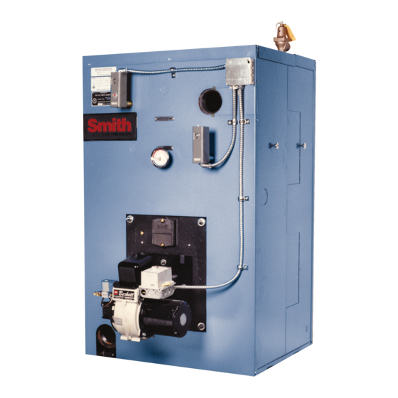
SERIES 19HE BOILER
PRESSURIZED FOR FIRING OIL, GAS
DESIGNED AND TESTED ACCORDING TO THE A.S.M.E. BOILER AND PRESSURE
VESSEL CODE, SECTION IV FOR MAXIMUM ALLOWABLE WORKING PRESSURE.
STEAM - 15 PSIG, WATER - 80 PSIG
NOTE: READ THESE INSTRUCTIONS CAREFULLY. THEY WILL
SAVE YOU VALUABLE TIME WHEN ASSEMBLING THE BOILER.
CAUTION: Do not use automotive anti-freeze in boiler waterways. If necessary to
use anti-freeze, be sure to employ a preparation designed for hydronic heating
systems such as ethylene or propylene glycol.
Water treatment is not recommended. This boiler uses gaskets to seal the ports
of adjoining sections. These gaskets are made of a fl uorocarbon elastomer
(designation FKM) marketed under the brand name Viton. Consult a water
treatment professional before adding any chemical to the boiler water. Any
water treatment or anti-freeze added to the system must be compatible with the
Viton gaskets.
THE SECTIONS OF THIS BOILER MUST BE ASSEMBLED
TO THE PROPER TORQUE. READ INSTRUCTIONS
INSTALLER, THESE INSTRUCTIONS TO BE AFFIXED ADJACENT TO THE BOILER.
CONSUMER, RETAIN THESE INSTRUCTIONS FOR FUTURE REFERENCE PURPOSES.
FOR JACKET ASSEMBLY AND BURNER SET UP SEE SEPARATE INSTRUCTIONS.
INSTALLATION
INSTRUCTIONS
STEAM OR WATER HEATING
OR COMBINATION GAS/OIL
TO INSTALLER
WESTCAST, INC.
260 NORTH ELM STREET
WESTFIELD, MA 01085
TEL. (413) 562-9631 FAX (413) 562-3799
7555 TRANMERE DRIVE
MISSISSAUGA,ONTARIO L5S 1L4
TEL. (905) 672-2991 FAX (905) 672-2883
19IOM-7
Advertisement
Table of Contents

Related Manuals for Smith 19HE series


Summary of Contents for Smith 19HE series
- Page 1 19IOM-7 SERIES 19HE BOILER INSTALLATION INSTRUCTIONS STEAM OR WATER HEATING PRESSURIZED FOR FIRING OIL, GAS OR COMBINATION GAS/OIL DESIGNED AND TESTED ACCORDING TO THE A.S.M.E. BOILER AND PRESSURE VESSEL CODE, SECTION IV FOR MAXIMUM ALLOWABLE WORKING PRESSURE. STEAM - 15 PSIG, WATER - 80 PSIG TO INSTALLER NOTE: READ THESE INSTRUCTIONS CAREFULLY.
-
Page 2: Series 19He Exploded View
SERIES 19HE BOILER INSTALLATION INSTRUCTIONS SERIES 19HE REPLACEMENT PARTS Ref # Name of Part Part No. Ref # Name of Part Part No. Front Section 3638 10" Smokehood Assy. 70341 Plain Leg Section 3637 (8-12 Sect. 19 & 19A) Heater Leg Section 3641 Smokehood Tape 74300... - Page 3 19HE SERIES 19HE REPLACEMENT PARTS Ref # Name of Part Part No. Ref # Name of Part Part No. Cleanout Cover Assembly includes: " x 9" Draw Rod 60101 Cleanout Plate, Insulation and Rope " Hex Nut 60877 Clean Out Cover Plate Assy** 70361 "...
-
Page 4: Table Of Contents
SERIES 19HE BOILER INSTALLATION INSTRUCTIONS CONTENTS Table 1 Series 19HE Exploded View ..........page 2 Boiler No. Min. Recommended Pad Length Parts List ...............page 2 19HE-3 30" Table of Contents ............page 4 19HE-4 36" General Information ............page 4 19HE-5 42" Boiler Location ..............page 4 19HE-6 48"... -
Page 5: Combustion And Ventilation Air
SERIES 19HE BOILER INSTALLATION INSTRUCTIONS COMBUSTION AND VENTILATION AIR CAUTION: Due to the fact that the sections are top An adequate supply of air for the boiler room must be provided heavy, it is absolutely necessary that the back section to allow complete combustion of fuel and ventilation of the be supported in such a manner as to prevent its falling room to avoid excessively high ambient temperature. -
Page 6: Hydrostatic Test
If there is seepage about chaplets or minor leakage, consult Be certain the angle rails remain level and provide support the Smith Company representative for advice regarding for each section as it is assembled. Check each section for A.S.M.E. Code approved repairs by peening or plugging. -
Page 7: Water Piping
SERIES 19HE BOILER INSTALLATION INSTRUCTIONS Table 5 Figure 5 NUMBER EVAPOR. CONDENSATE WATER 1" MIN. FEED SYSTEM SUPPLY CHECK VALVE CONNECTIONS RATE RECEIVER BELOW WATER WATER PUMP SECTIONS CAP.-GAL. CIRCULATOR LEVEL GAL. RATE-GPM GATE VALVE 1.22 EXPANSION 1.70 TANK RELIEF VALVE 1.19 2.37 AIR REMOVAL... -
Page 8: Burner Mounting Plate
SERIES 19HE BOILER INSTALLATION INSTRUCTIONS The sealing rope should be placed in the groove on the Figure 6 - Tankless Piping boiler side of the plate using adhesive to hold it in place. The insulation block has a burner opening and a cutout for WATER SUPPLY the observation opening. -
Page 9: Cleanout Covers
(See Figure 10) same way. Figure 9 Figure 10 FOR DISCHARGE PIPING THROUGH ROOF CONSULT THE SMITH COMPANY RELIEF OR SAFETY VALVE SUPPORT DISCHARGE DO NOT REMOVE RATING PIPING SO AS TO AVOID OR WARNING TAGS. -
Page 10: Cleaning Boiler Waterways
0.10 ins. w.c. at cleaning the boiler. the boiler outlet, consult the Smith Co. for verifi cation of burner size. If the chimney has the ability to develop excess draft, a 1. Add an approved boiler compound. Follow the compound barometric draft control should be installed in the chimney. -
Page 11: Control Tappings Diagram
SERIES 19HE BOILER INSTALLATION INSTRUCTIONS Figure 11 - Tapping and Control Locations VENT CONNECTION SERIES 19HE BOILER (STEAM) TAPPING AND CONTROL LOCATIONS 12" (OUTLET) 3" SUPPLY TAPS ADAPTER COLLAR “A” - 1" TAP, PRESSURE CONTROLS ( 11 & 12 SECTION ONLY ) “B”... -
Page 12: Warning
Carbon Monoxide (CO) is a gas which is odorless, colorless and tasteless but is very toxic. If your Smith boiler is not working properly, or is not vented properly, dangerous levels of CO may accumulate. CO is lighter than air and thus may travel throughout the building. BRIEF EXPOSURE TO HIGH CONCENTRATIONS OF CO, OR PROLONGED EXPOSURE TO LESSER AMOUNTS OF CO MAY RESULT IN CARBON MONOXIDE POISONING.
Need help?
Do you have a question about the 19HE series and is the answer not in the manual?
Questions and answers