APRILIA Mojito 50 Workshop Manual
Hide thumbs
Also See for Mojito 50:
- Owner's manual (118 pages) ,
- Manual (576 pages) ,
- Manual (185 pages)
Table of Contents
Advertisement
Quick Links
Advertisement
Chapters
Table of Contents

Related Manuals for APRILIA Mojito 50


Summary of Contents for APRILIA Mojito 50
- Page 1 MOJITO 50 - 125 - 150 1149 3 00/2003-11 workshopmanual...
- Page 2 INTRODUCTION MOJITO 50 - 125 - 150 INTRODUCTION 0 - 1...
- Page 3 INTRODUCTION MOJITO 50 - 125 - 150 CONTENTS 0.1. FOREWORD ..............................3 0.1.1. FOREWORD............................... 3 0.1.2. REFERENCE MANUALS..........................4 0.1.3. ABBREVIATIONS AND SYMBOLS ......................5 0 - 2...
-
Page 4: Foreword
ASSISTANCE DEPARTMENT, who will be able to provide any information you require in this regard, as well as providing information on updates and technical modifications to the motorcycle. The aprilia s.p.a. Company reserves the right to make changes to its models at any time, without prejudice to the essential characteristics described and illustrated in this manual. -
Page 5: Reference Manuals
INTRODUCTION MOJITO 50 – 125 - 150 0.1.2. REFERENCE MANUALS 125-150 cc VERSION 50 cc VERSION WORKSHOP ENGINE MANUALS WORKSHOP ENGINE MANUALS aprilia part # (description) aprilia part # (description) 8140680 8140433 8140681 8140436 8140682 8140434 8140683 8140435 8140684 8140437... -
Page 6: Abbreviations And Symbols
INTRODUCTION MOJITO 50 - 125 - 150 0.1.3. ABBREVIATIONS AND SYMBOLS = number < = less than > = greater than = equal to or less than = equal to or greater than = approximately ∞ = infinite °C = degrees Celsius (centigrade) °F... - Page 7 INTRODUCTION MOJITO 50 - 125 - 150 RIGHT SIDE = right side = Society of Automotive Engineers TEST = diagnostic test T.B.E.I. = crowned head with flush-mounted hexagonal bolt T.C.E.I. = cylinder head with flush-mounted hexagonal bolt T.E. = hexagonal head T.P.
- Page 8 GENERAL INFORMATION MOJITO 50 - 125 - 150 GENERAL INFORMATION 1 - 1...
-
Page 9: Table Of Contents
GENERAL INFORMATION MOJITO 50 - 125 - 150 CONTENTS 1.1. STRUCTURE OF THIS MANUAL....................3 1.1.1. HOW TO CONSULT THIS MANUAL..................3 1.1.2. SAFETY MESSAGES......................4 1.2. GENERAL INSTRUCTIONS......................5 1.2.1. GENERAL SAFETY RULES ....................5 1.3. DANGEROUS ELEMENTS ......................8 1.3.1. WARNINGS..........................8 1.4. RUNNING IN ..........................11 1.4.1. -
Page 10: Structure Of This Manual
GENERAL INFORMATION MOJITO 50 - 125 - 150 1.1. STRUCTURE OF THIS MANUAL 1.1.1. HOW TO CONSULT THIS MANUAL • This manual is broken down into sections and chapters, each of which corresponds to a major category of compo- nents. To consult the manual, see the contents indicating the sections. Per . -
Page 11: Safety Messages
GENERAL INFORMATION MOJITO 50 - 125 - 150 1.1.2. SAFETY MESSAGES The following warning symbols are used throughout the manual to indicate the following: Warning symbol relating to safety. When this symbol is seen on the motorcycle or in the manual, be careful of the potential risk of injury. -
Page 12: General Instructions
GENERAL INFORMATION MOJITO 50 - 125 - 150 1.2. GENERAL INSTRUCTIONS 1.2.1. GENERAL SAFETY RULES CARBON MONOXIDE If you have to run the engine to be able to complete any task, make sure that this is done in the open air or in a room that is well ventilated. - Page 13 GENERAL INFORMATION MOJITO 50 - 125 - 150 HYDROGEN GAS AND BATTERY ELECTROLYTE DANGER Battery electrolyte is toxic and caustic, and if it comes into contact with the skin it may cause burns as it contains sulphuric acid. Always wear close-fitting gloves and protective clothing when handling battery electrolyte.
- Page 14 GENERAL INFORMATION MOJITO 50 - 125 - 150 DISASSEMBLING COMPONENTS Do not loosen and/or tighten bolts and nuts using pliers or any other tools – always use the correct spanner. Mark the positions of all the connection joints (hoses, cables, etc.) before separating them, and identify them by u- sing different markings.
-
Page 15: Dangerous Elements
GENERAL INFORMATION MOJITO 50 - 125 - 150 1.3. DANGEROUS ELEMENTS 1.3.1. WARNINGS FUEL DANGER Fuel used to drive internal combustion engines is highly inflammable and may become explosive un- der certain conditions. It is best to refuel and carry out maintenance in well ventilated places with the engine switched off. - Page 16 GENERAL INFORMATION MOJITO 50 - 125 - 150 BRAKE FLUID IMPORTANT This vehicle is fitted with front and rear disc brakes with separate hydraulic circuits. The information below refers to a single braking system but is valid for both. DANGER Do not use the vehicle if the brakes are worn or are not working properly.
- Page 17 GENERAL INFORMATION MOJITO 50 - 125 - 150 TYRES WARNING An over inflated tyre will make the ride harder and uncomfortable, compromising rising comfort. In addition road handling will be compromised, especially on bends and on wet roads. A tyre that is under inflated (pressure too low) may slip on the wheel rim causing the rider to lose con- trol of the vehicle.
-
Page 18: Running In
After the first 1000 km (625 mi), progressively increase speed until maximum performance is reached. WARNING After the first 500 km (312 mi) for the Mojito 50 and the first 1000 km (621 mi) for the Mojito 125–150, carry out the checks listed in the “end of running in” column (see ROUTINE MAINTENANCE TABLE), in order to avoid harming yourself, others, and/or the vehicle. -
Page 19: Vehicle Identification
GENERAL INFORMATION MOJITO 50 - 125 - 150 1.5. VEHICLE IDENTIFICATION 1.5.1. POSITION OF SERIAL NUMBERS These numbers are required for registering the vehicle. IMPORTANT Altering these identification numbers may lead to strict penal and administrative fines being incurred. Changing the chassis number result sin the guarantee be- coming null and void immediately. - Page 20 50 CC VERSION MOJITO 50 - 125 - 150 50 CC VERSION 2 - 1...
- Page 21 REMOVING THE REAR COWLING ..................35 2.5.8. FRONT BRAKING SYSTEM DIAGRAM................... 37 2.5.9. REAR BRAKING SYSTEM DIAGRAM ..................38 2.6. SYSTEM DIAGRAM ........................39 2.6.1. WIRING DIAGRAM – MOJITO 50 ................... 39 2.6.2. WIRING DIAGRAM – MOJITO CUSTOM 50 ................41 2 - 2...
-
Page 22: Technical Information
50 CC VERSION MOJITO 50 - 125 - 150 2.1. TECHNICAL INFORMATION 2.1.1. TECHNICAL DATA DIMENSIONS Max. length 1900 mm Max. length MOJITO CUSTOM 1950 mm Max. width 720 mm Max. width MOJITO CUSTOM 900 mm Seat height 745 mm... - Page 23 50 CC VERSION MOJITO 50 - 125 - 150 SUSPENSIONS Front Hanger fork Stroke 50 mm Rear Hydraulic shock absorber Stroke 67.5 mm BRAKES Front Disc - Ø190 mm with hydraulic transmission Rear Drum - Ø120 mm with mechanic transmission...
-
Page 24: Fixing Elements
50 CC VERSION MOJITO 50 - 125 - 150 2.1.2. FIXING ELEMENTS WARNING The fixing elements indicated in the table must be tightened to the torque indicated using a torque ® wrench and LOCTITE where indicated. Notes: ® L243=apply Loctite... -
Page 25: Lubricant Table
50 CC VERSION MOJITO 50 - 125 - 150 2.1.3. LUBRICANT TABLE LUBRICANT PRODUCT Transmission oil RECOMMENDED: F.C., SAE 75W 90 or GEAR SYNTH, SAE 75W - 90 As an alternative to the recommended oil, it is possible to use high-quality oils with characteristics in compliance with or superior to the A.P.I. -
Page 26: Arrangement Of The Main Elements
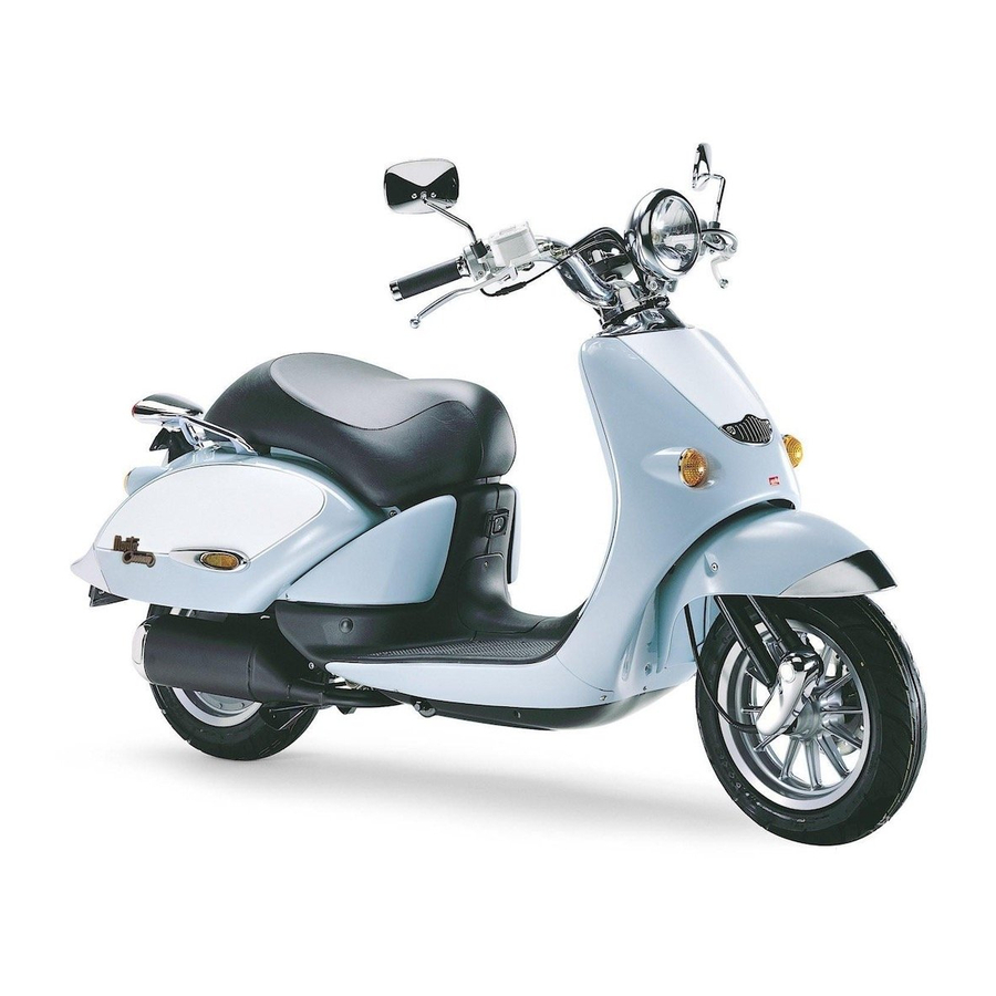
50 CC VERSION MOJITO 50 - 125 - 150 2.1.4. ARRANGEMENT OF THE MAIN ELEMENTS Key: Left rear-view mirror (M50 not provided in the UK version) Left inspection cover Central inspection cover Glove compartment Battery Fuse carrier Passenger grab rail... - Page 27 Right inspection cover Right rear-view mirror (M50 in the countries where required) Brake fluid reservoir (front brake) Horn 10. Fuel tank 11. Anti-theft hook [for the “ aprilia Body-Guard armoured cable (OPT)] 12. 2 stroke oil tank. 2 - 8...
-
Page 28: Routine Maintenance Operations
50 CC VERSION MOJITO 50 - 125 - 150 2.2. ROUTINE MAINTENANCE OPERATIONS 2.2.1. ROUTINE MAINTENANCE CHART After running- Every 4000 km Every 8000 km Components (2500mi) or (5000 mi) or [500 km 12 months 24 months (312 mi)] Rear shock absorber Transmission cables and controls Battery –... -
Page 29: Air Cleaner
50 CC VERSION MOJITO 50 - 125 - 150 2.2.2. AIR CLEANER Clean the air cleaner every 4000 km (2500 mi) or 12 months. If the vehicle is used on dusty or wet roads, the cleaning op- erations and replacement should be carried out more fre- quently. -
Page 30: Idling Adjustment
50 CC VERSION MOJITO 50 - 125 - 150 2.2.3. IDLING ADJUSTMENT Adjust the idling after the first 500 km (312 mi) and every time it is irregular. Before adjusting the carburettor make sure that it is properly lubricated, that the spark plug is in good condition, the air cleaner is clean and airtight, and that the exhaust system is completely airtight. -
Page 31: Spark Plug
50 CC VERSION MOJITO 50 - 125 - 150 2.2.4. SPARK PLUG THIGHTENING TORQUE Spark plug: 20 Nm (2 kgm). Check the spark plug after the first 500 km (312 mi) and suc- cessively every 4000 km (2500 mi). Change it every 8000 km (5000 mi). - Page 32 50 CC VERSION MOJITO 50 - 125 - 150 WARNING The spark plug must be well tightened, other- wise the engine may overheat and be seriously damaged. Use the recommended type of spark plug only, otherwise the life and performance of the engine may be compromised.
-
Page 33: Fuel Supply
50 CC VERSION MOJITO 50 - 125 - 150 2.3. FUEL SUPPLY 2.3.1. CARBURETTOR DIAGRAM Key: 27. Jet holder Gas valve cover 28. Clamp Gasket 29. Idle jet Spring 30. Hose Plate 31. O-Ring Metering rod lock 32. Pipe fitting 33. -
Page 34: Removing The Carburettor
50 CC VERSION MOJITO 50 - 125 - 150 2.3.2. REMOVING THE CARBURETTOR • Remove the right and left inspection covers – see 2.5.6 (REMOVING THE RIGHT AND LEFT INSPECTION COVERS) • Remove the rear cowling – see 2.5.6 (REMOVING THE REAR COWLING) •... - Page 35 50 CC VERSION MOJITO 50 - 125 - 150 • Disconnect the automatic starter connector. • Release the hose clamp that fixes the carburettor to the filter casing. • Unscrew and remove the two fixing screws for the in- take manifold.
-
Page 36: Removing The Fuel Level Sensor
50 CC VERSION MOJITO 50 - 125 - 150 2.3.3. REMOVING THE FUEL LEVEL SENSOR • Unscrew and remove the fixing screws for the fuel level sensor cover. • Remove the cover. • Disconnect the electrical connector. • Unscrew and remove the four fixing nuts for the sen- sor. -
Page 37: Removing The Fuel Tank
50 CC VERSION MOJITO 50 - 125 - 150 2.3.4. REMOVING THE FUEL TANK • Remove the right and left inspection covers – see 2.5.6 (REMOVING THE RIGHT AND LEFT INSPECTION COVERS) • Unscrew and remove the fixing screw for the fuel level sensor cover. - Page 38 50 CC VERSION MOJITO 50 - 125 - 150 • Release the retention hose clamp and remove the fuel tank breather pipe. • Working on both sides, unscrew and remove the two front fixing screws for the lower floor panel guards.
- Page 39 50 CC VERSION MOJITO 50 - 125 - 150 • Unscrew and remove the four fixing screws for the tank. • Working on both sides, unscrew and remove the two fixing screws for the body support bracket. • Remove the brackets.
- Page 40 50 CC VERSION MOJITO 50 - 125 - 150 • Pull the fuel filler cap downwards and remove it from the right side. • Release the hose clamp (1) and disconnect the fuel pipe (2). • Remove the fuel filler cap.
-
Page 41: Engine
50 CC VERSION MOJITO 50 - 125 - 150 2.4. ENGINE 2.4.1. REMOVING THE ENGINE WARNING Before proceeding with these operations, re- member that the engine must be removed downwards from the frame. Arrange the nec- essary equipment accordingly. •... - Page 42 50 CC VERSION MOJITO 50 - 125 - 150 • Remove the gas cable from the carburettor. • Disconnect the automatic starter connector. • Release the clamp and disconnect the fuel supply pip- ing. WARNING When removing the fuel supply pipe and the vacuum pipe, mark them to avoid inverting them accidentally when refitting the engine.
- Page 43 50 CC VERSION MOJITO 50 - 125 - 150 • Release the clamp and disconnect the mixer oil pipe. WARNING Fold the mixer oil pipe over and secure it with a self-locking clamp to prevent the oil spilling. • Remove the battery, fuel tank, and carburettor breather pipes from the guide eyelet.
- Page 44 50 CC VERSION MOJITO 50 - 125 - 150 • Unscrew the screw (1) and remove the brake cable seal hose clamp. • Unscrew and remove the screw (2). • Disconnect the earth cable (3). • Remove the cap (4) from the spark plug (5) .
- Page 45 50 CC VERSION MOJITO 50 - 125 - 150 • Working from the right, unscrew and remove the nut (6). • Remove the pin from the opposite side. • Remove the engine, complete with the central stand and rear wheel.
-
Page 46: Cycle Characteristics
50 CC VERSION MOJITO 50 - 125 - 150 2.5. CYCLE CHARACTERISTICS 2.5.1. FRONT FORK DIAGRAM Key: O-Ring 115 Special washer Washer 13x24x2.5 M12 low self-locking nut Bush Nylon bush D20 cup Bush 10. M8 low self-locking nut 11. M8x35 hex screw 12. -
Page 47: Removing The Fork
50 CC VERSION MOJITO 50 - 125 - 150 2.5.2. REMOVING THE FORK • Place the vehicle on the central stand on a hoist with the front wheel protruding beyond the edge of the hoist board. • Place the vehicle on the central stand on a hoist with the front wheel protruding beyond the edge of the hoist board. - Page 48 50 CC VERSION MOJITO 50 - 125 - 150 If necessary, the front shock absorbers can now be removed. REMOVING THE SHOCK ABSORBERS • Unscrew and remove the two fixing screws for the shock absorbers. • Remove the shock absorber.
-
Page 49: Front Body Diagram
50 CC VERSION MOJITO 50 - 125 - 150 2.5.3. FRONT BODY DIAGRAM Key: 22. M4x10 hex socket screw Right electrical control place 23. 4.3x9x0.8 washer Left electrical control place 24. Panel, chr. (Mojito Custom) Self-tapping screw . 25. Front mudguard Headlight chromed ring nut (Mojito Retrò) -
Page 50: Central Body Diagram
50 CC VERSION MOJITO 50 - 125 - 150 2.5.4. CENTRAL BODY DIAGRAM Key: Glove compartment door Top box gasket Glove compartment Self-tapping screwstic . Front glove compartment lock Lock nut 5.5x15.9 cap screw Black floor panel Type appr. data cover 10. -
Page 51: Rear Body Diagram
50 CC VERSION MOJITO 50 - 125 - 150 2.5.5. REAR BODY DIAGRAM 2 - 32... - Page 52 50 CC VERSION MOJITO 50 - 125 - 150 Key: 23. Rear reflector RH undersaddle 24. 4.3x12x1 washer RH side cover 25. M4 low self-locking nut LH side cover 26. M4x12 cap screw LH undersaddle 27. Rear bumper Undersaddle hook 28.
-
Page 53: Removing The Right And Left Inspection Covers
50 CC VERSION MOJITO 50 - 125 - 150 2.5.6. REMOVING THE RIGHT AND LEFT IN- SPECTION COVERS • Lift the saddle. • Working on both sides, unscrew and remove the two fixing screws for the left and right inspection covers. -
Page 54: Removing The Rear Cowling
50 CC VERSION MOJITO 50 - 125 - 150 2.5.7. REMOVING THE REAR COWLING • Lift the saddle. • Unscrew and remove the five fixing rear handle screws. • Remove the handle from the rear engine cowling. WARNING Handle chromed and painted components care- fully so as not to scratch or ruin them. - Page 55 50 CC VERSION MOJITO 50 - 125 - 150 • Unscrew and remove the three fixing screws for the reflector support. • Remove the support. • Unscrew and remove the rear fixing bolt for the engine cowling. • Disconnect the taillight wiring connector.
-
Page 56: Front Braking System Diagram
50 CC VERSION MOJITO 50 - 125 - 150 2.5.8. FRONT BRAKING SYSTEM DIAGRAM Key: Front brake pump D12 (Mojito Retrò) Brake lever (Mojito Retrò) Brake lever pin Cap screw (Mojito Retrò) Brake lever stand (Mojito Retrò) Pump cover (Mojito Retrò) -
Page 57: Rear Braking System Diagram
50 CC VERSION MOJITO 50 - 125 - 150 2.5.9. REAR BRAKING SYSTEM DIAGRAM Key: Rear brake lever complete (Mojito Custom) Rear brake lever (Mojito Custom) Brake lever pin (Mojito Custom) U-bolt (Mojito Custom) Screw (Mojito Custom) Brake light switch... -
Page 58: System Diagram
50 CC VERSION MOJITO 50 - 125 - 150 2.6. SYSTEM DIAGRAM 2.6.1. WIRING DIAGRAM – MOJITO 50 2 - 39... - Page 59 50 CC VERSION MOJITO 50 - 125 - 150 Key: WIRE COLOURS Generator orange light blue Spark plug blue HT Coil white Voltage Regulator yellow Battery grey Starter motor brown Start Relay black Front stoplight switch 10. Rear stoplight switch green 11.
- Page 60 50 CC VERSION MOJITO 50 - 125 - 150 2.6.2. WIRING DIAGRAM – MOJITO CUSTOM 50 2 - 41...
- Page 61 50 CC VERSION MOJITO 50 - 125 - 150 Key: WIRE COLOURS Generator orange light blue Spark plug blue HT Coil white Voltage Regulator yellow Battery grey Starter motor brown Start Relay black Front stoplight switch 10. Rear stoplight switch green 11.
- Page 62 125 - 150 CC VERSION MOJITO 50 - 125 - 150 125 - 150 CC VERSION 3 - 1...
- Page 63 125 - 150 CC VERSION MOJITO 50 - 125 - 150 CONTENTS 3.1. TECHNICAL INFORMATION..........................3 3.1.1. TECHNICAL DATA............................ 3 3.1.2. FIXING ELEMENTS ..........................5 3.1.3. LUBRICANT TABLE ..........................6 3.1.4. ARRANGEMENT OF THE MAIN ELEMENTS................... 7 3.2. ROUTINE MAINTENANCE OPERATIONS ...................... 9 3.2.1.
-
Page 64: Technical Information
125 - 150 CC VERSION MOJITO 50 - 125 - 150 3.1. TECHNICAL INFORMATION 3.1.1. TECHNICAL DATA DIMENSIONS Max. length 1980 mm Max. width 720 mm Max. width for the MOJITO CUSTOM 920 mm Seat height 780 mm Seat height for the MOJITO CUSTOM 755 mm Max. - Page 65 125 - 150 CC VERSION MOJITO 50 - 125 - 150 SUSPENSIONS Front Fork with connection elements Stroke 50 mm Rear Hydraulic mono-shock absorber Stroke 72 mm BRAKES Front Disc brake, Ø 190 mm with hydraulic transmission Rear Drum brake, Ø 140 mm with mechanic transmission...
-
Page 66: Fixing Elements
125 - 150 CC VERSION MOJITO 50 - 125 - 150 3.1.2. FIXING ELEMENTS WARNING The fixings indicated in the table must be tightened to the torque indicated using a torque wrench and ® LOCTITE where indicated. Notes: ® L243=apply Loctite... -
Page 67: Lubricant Table
125 - 150 CC VERSION MOJITO 50 - 125 - 150 3.1.3. LUBRICANT TABLE LUBRICANT PRODUCT Transmission oil RECOMMENDED: F.C., SAE 75W 90 or GEAR SYNTH, SAE 75W - 90 As an alternative to the recommended oil, it is possible to use high quality oils with characteristics in compliance with or superior to the A.P.I. -
Page 68: Arrangement Of The Main Elements
125 - 150 CC VERSION MOJITO 50 - 125 - 150 3.1.4. ARRANGEMENT OF THE MAIN ELEMENTS Key: Left rear-view mirror Glove compartment Left inspection cover Central inspection cover Passenger left footrest Air cleaner Passenger grab rail Saddle lock Central stand 10. - Page 69 Ignition switch / steering lock Bag hook Fuse box Right rear-view mirror Brake fluid reservoir (front brake) Horn 10. Fuel tank 11. Anti-theft hook [for the “ aprilia Body-Guard armoured cable (OPT)] 12. Spark plug 13. Passenger right footrest 3 - 8...
-
Page 70: Routine Maintenance Operations
125 - 150 CC VERSION MOJITO 50 - 125 - 150 3.2. ROUTINE MAINTENANCE OPERATIONS 3.2.1. ROUTINE MAINTENANCE CHART After running- Every 6000 km Every 12000 km Components (3750 mi) or (7500 mi) or [1000 km 12 months 24 months... -
Page 71: Air Cleaner
125 - 150 CC VERSION MOJITO 50 - 125 - 150 3.2.2. AIR CLEANER Clean the air filter every 6000 km (3750 mi) or 12 months. If the vehicle is used on dusty or wet roads, the cleaning and replacement operations should be carried out more fre- quently. -
Page 72: Idling Adjustment
125 - 150 CC VERSION MOJITO 50 - 125 - 150 3.2.3. IDLING ADJUSTMENT • Idling does not have to be adjusted on the engine very often, but when this is done, it must be carried out in full compliance with a few standards. - Page 73 125 - 150 CC VERSION MOJITO 50 - 125 - 150 • Using the analyser revolution counter or a separate revolution counter, turn the idling screw until an engine speed of 1600 - 1700 rpm is obtained. IMPORTANT The ignition system works on a spark advance and provides significant power.
-
Page 74: Spark Plug
125 - 150 CC VERSION MOJITO 50 - 125 - 150 3.2.4. SPARK PLUG TIGHTENING TORQUE Spark plug: 12-14 Nm (1.2-1.4 kgm). Check the spark plug after the first 1000 km (625 mi) and successively every 6000 km (3750 mi). Change it every 12000 km (7500 mi). - Page 75 125 - 150 CC VERSION MOJITO 50 - 125 - 150 WARNING The spark plug must be well tightened, other- wise the engine may overheat and be seriously damaged. Use the recommend type of spark plug or oth- erwise the life and performance of the engine may be compromised.
-
Page 76: Checking The Engine Oil Level And Topping Up
125 - 150 CC VERSION MOJITO 50 - 125 - 150 3.2.5. CHECKING THE ENGINE OIL LEVEL AND TOPPING UP Check the engine oil level from time to time. Change it after the first 1000 km (625 mi) and successively every 3000 km (1875 mi) see 3.2.6 (CHANGING THE ENGINE OIL AND... -
Page 77: Changing The Engine Oil And The Engine Oil Filter
125 - 150 CC VERSION MOJITO 50 - 125 - 150 3.2.6. CHANGING THE ENGINE OIL AND THE ENGINE OIL FILTER Change the engine oil filter after the first 1000 km (621 mi), that is, on completing running in, and then every 3000 km (1875 mi). -
Page 78: Fuel Supply
125 - 150 CC VERSION MOJITO 50 - 125 - 150 3.3. FUEL SUPPLY 3.3.1. CARBURETTOR DIAGRAM Key: 28. Complete sump Lever 29. Bellows Screw 30. Bush Spring 31. Sump drain screw Screw 32. Heater kit Spring 33. Membrane Complete automatic starter 34. -
Page 79: Removing The Carburettor
125 - 150 CC VERSION MOJITO 50 - 125 - 150 3.3.2. REMOVING THE CARBURETTOR • Lift the saddle. • Unscrew and remove the two fixing screws for the car- burettor cover. • Remove the cover. • Release the two clamps that attach the carburettor to the air filter housing and the intake manifold. - Page 80 125 - 150 CC VERSION MOJITO 50 - 125 - 150 • Remove the carburettor from its seating. • Disconnect the gas cable. • Remove the carburettor. 3 - 19...
-
Page 81: Removing The Fuel Level Sensor
125 - 150 CC VERSION MOJITO 50 - 125 - 150 3.3.3. REMOVING THE FUEL LEVEL SENSOR • Unscrew and remove the fixing screws for the fuel level sensor cover. • Remove the cover. • Disconnect the electrical connector. •... -
Page 82: Removing The Fuel Tank
125 - 150 CC VERSION MOJITO 50 - 125 - 150 3.3.4. REMOVING THE FUEL TANK • Remove the lower guard – see 3.5.4 (BODY DIA- GRAM). • Unscrew and remove the fixing screws for the fuel level sensor cover. - Page 83 125 - 150 CC VERSION MOJITO 50 - 125 - 150 DANGER Danger of fire. Wait for the engine and the exhaust silencer to cool down completely. Fuel vapours are harmful to your health. Before starting work make sure that the room you are working in is adequately ventilated.
- Page 84 125 - 150 CC VERSION MOJITO 50 - 125 - 150 • Working on both sides, unscrew and remove the two fixing screws for the fairing support bracket. • Remove the lower fuel tank. UPPER TANK • Remove the fuel cap (1).
-
Page 85: Engine
125 - 150 CC VERSION MOJITO 50 - 125 - 150 3.4. ENGINE 3.4.1. REMOVING THE ENGINE WARNING Before proceeding with these operations, re- member that the engine must be removed downwards from the frame. Arrange the neces- sary equipment accordingly. - Page 86 125 - 150 CC VERSION MOJITO 50 - 125 - 150 • Disconnect the pick-up • Disconnect the heater connector. • Disconnect the automatic starter connector • Disconnect the starter motor connector. • Unscrew and remove the screw (1) and disconnect the earth cable.
- Page 87 125 - 150 CC VERSION MOJITO 50 - 125 - 150 IMPORTANT Set up a hoist and belts for lifting beforehand. • Connect the belts to the rear of the frame. • Lift the arm of the hoist until the belts are tensioned.
- Page 88 125 - 150 CC VERSION MOJITO 50 - 125 - 150 • Move the left underpanel. • Unscrew and remove the upper screw. • Remove the silent-block support plate. • Working from the left, unscrew and remove the nut (2).
-
Page 89: Cycle Characteristics
125 - 150 CC VERSION MOJITO 50 - 125 - 150 3.5. CYCLE CHARACTERISTICS 3.5.1. FRONT FORK DIAGRAM Key: 13. Washer 8.4x17 Front fork 14. Special washer Complete fork 15. O-Ring 115 Upper shock absorber cover 16. Cap Lower shock absorber cover 17. -
Page 90: Removing The Fork
125 - 150 CC VERSION MOJITO 50 - 125 - 150 3.5.2. REMOVING THE FORK • Place the vehicle on the central stand on a hoist with the front wheel protruding beyond the edge of the hoist surface. • Secure the back of the vehicle to the hoist using straps. - Page 91 125 - 150 CC VERSION MOJITO 50 - 125 - 150 If necessary the front shock absorbers can now be removed. REMOVING THE SHOCK ABSORBERS • Unscrew and remove the two fixing screws for the shock absorbers. • Remove the shock absorber.
-
Page 92: Front Body Diagram
125 - 150 CC VERSION MOJITO 50 - 125 - 150 3.5.3. FRONT BODY DIAGRAM Key: 26. M6x16 screw w/flange Headlight chromed ring nut 27. M5x16 screw w/flange Headlight support 28. 4.3x12x1 washer Dashboard panel 29. T bush Dashboard chromed ring nut 30. -
Page 93: Central Body Diagram
125 - 150 CC VERSION MOJITO 50 - 125 - 150 3.5.4. CENTRAL BODY DIAGRAM Key: 20. LH side panel Glove compartment door 21. Lower protective fairing Top box gasket 22. Clip for self-tapping screw D4,2 Glove compartment 23. Clip for self-tapping screw D5,5 Self-tapping screw . -
Page 94: Rear Body Diagram
125 - 150 CC VERSION MOJITO 50 - 125 - 150 3.5.5. REAR BODY DIAGRAM Key: RH side cover 30. Insulating washer LH side cover 31. M6x16 screw w/flange Under saddle hook, cpl. 32. 8.4x13 washer M4x35 cap screw 33. Bush 4.2x16 cap screw... -
Page 95: Removing The Right And Left Inspection Covers
125 - 150 CC VERSION MOJITO 50 - 125 - 150 3.5.6. REMOVING THE RIGHT AND LEFT IN- SPECTION COVERS • Lift the saddle. • Working on both sides, unscrew and remove the two fixing screws for the left and right inspection covers. -
Page 96: Removing The Rear Cowling
125 - 150 CC VERSION MOJITO 50 - 125 - 150 3.5.7. REMOVING THE REAR COWLING • Lift the saddle. • Unscrew and remove the five screws. • Remove the rear handle from the engine cowling. WARNING Handle chromed and painted components care- fully so as not to scratch or ruin them. - Page 97 125 - 150 CC VERSION MOJITO 50 - 125 - 150 • Unscrew and remove the three fixing screws for the reflector support. • Remove the support. • Unscrew and remove the rear fixing bolt for the engine cowling. •...
-
Page 98: Front Braking System Diagram
125 - 150 CC VERSION MOJITO 50 - 125 - 150 3.5.8. FRONT BRAKING SYSTEM DIAGRAM Key: 22. Bleeder +cap Front wheel 23. Caliper pin + spring Front tyre 120/70-12 24. M8x25 screw w/flange Tubeless valve 25. F. anti-whistle plate-pair Brake disc D190 26. -
Page 99: Rear Braking System Diagram
125 - 150 CC VERSION MOJITO 50 - 125 - 150 3.5.9. REAR BRAKING SYSTEM DIAGRAM Key: Rear wheel 28. Rear brake lever complete (Mojito Custom) Tubeless valve 29. Rear brake lever (Mojito Custom) Rear tyre 130/70-12” 30. Brake lever pin (Mojito Custom) Ring 31. -
Page 100: Electrical System
125 - 150 CC VERSION MOJITO 50 - 125 - 150 3.6. ELECTRICAL SYSTEM 3.6.1. COMPONENT CHECK Control Unit: The ignition control unit is of a capacitative discharge type, with the ignition advance being controlled digitally in relation to the engine speed. The control unit has two connectors, of which the eight-way connector is used. - Page 101 125 - 150 CC VERSION MOJITO 50 - 125 - 150 Generator: three-phase alternator winding resistance 1 Ω output voltage 40Vac (measured with the generator discon- nected from the electrical system and the engine at 3000 rpm) charging voltage: 13.8 V to be measured at the battery poles (with the engine at 3000 rpm).
- Page 102 125 - 150 CC VERSION MOJITO 50 - 125 - 150 Automatic starter: resistance 25-30 Ω Fuel heater: resistance 10-15 Ω 3 - 41...
-
Page 103: Wiring Diagram - Mojito 125 - 150
125 - 150 CC VERSION MOJITO 50 - 125 - 150 3.6.2. WIRING DIAGRAM – MOJITO 125 - 150 3 - 42... - Page 104 125 - 150 CC VERSION MOJITO 50 - 125 - 150 Key: WIRE COLOURS Fuel level sensor orange Multiple connectors light blue Low fuel warning light blue Turn indicator pilot light white Parking light pilot light yellow Instrument panel lights...
- Page 105 G.Galilei, 1 30033 Noale (VE) Italy tel. +39 041.5829111 fax +39 041.5829190 www.aprilia.com www.serviceaprilia.com...