Table of Contents
Advertisement
Advertisement
Table of Contents

Related Manuals for SoundCraft B800


Summary of Contents for SoundCraft B800
- Page 1 SOUNDCRAFT User Guide...
- Page 2 Information in this manual is subject to change without notice and does not represent a commitment on the part of the vendor. Soundcraft shall not be liable for loss or damage whatsoever arising from the use of information or any error contained in this manual.
-
Page 3: Table Of Contents
1.Introduction Introduction Warranty 2. Installation Dimensions Meterbridge EDAC Connectors Rear Connector Panel D-type Connectors Jumper Options Internal Monitor Source Selection 2.12 3. Block Diagrams Mono Input Block Diagram Group Module Block Diagram Stereo Input Block Diagram Stereo Group Module Block Diagram ST1 /ST2 Master Block diagram Monitor Block Diagram Comms Block Diagram... - Page 4 Master ST1 & ST2 Modules 4.22 Monitor Module 4.26 Communication Module 4.30 Meterbridge Modules 4.34 5.Specifications...
-
Page 5: Introduction
1.Introduction B800 Introduction... -
Page 6: Introduction
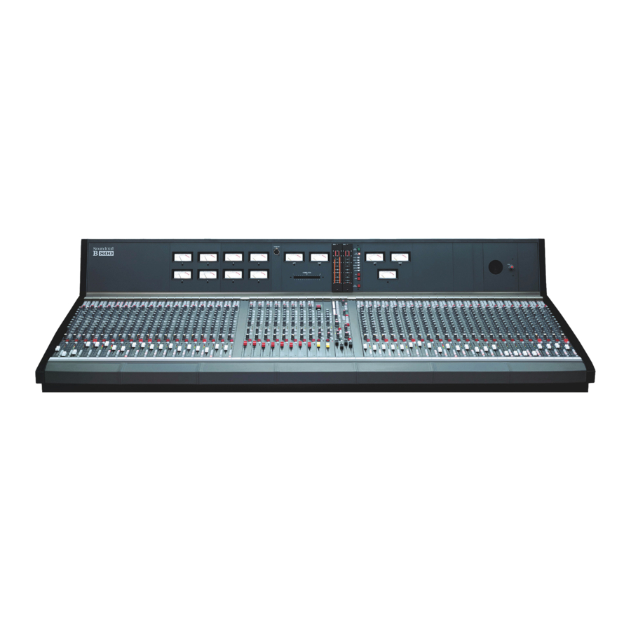
B800 Congratulations on purchasing a Soundcraft console. The B800 has been designed to meet today’s needs of Live TV & Radio Broadcast and Production Facilities including OB vehicles. System Features The B800 features: • 5 frame sizes: 24, 32, 40, 48 and 56 module-widths are available. -
Page 7: Warranty
Equipment has been properly installed in accordance with instructions contained in Soundcraft’s manual; and b) the End User has notified Soundcraft or the Dealer within 14 days of the defect appearing; and c) no persons other than authorised representatives of Soundcraft or the Dealer have effected any replacement of parts maintenance adjustments or repairs to the Equipment;... - Page 8 B800 Introduction...
-
Page 9: Installation
2. Installation B800 Installation... - Page 10 B800 Installation...
-
Page 11: Meterbridge
There are also 2 additional XLRs. The first of this is commonly used to connect the T/B Mic feed from the meterbridge to the T/Binput in the console, via the XLR on the flying lead. The second XLR is for future expansion. B800 Installation... - Page 12 CCT 6 CCT 7 CCT 8 CCT 9 CCT 10 CCT 11 CCT 12 CCT 13 CCT 14 CCT 15 CCT 16 CCT 17 CCT 18 CCT 19 CCT 20 CCT 21 CCT 22 CCT 23 CCT 24 B800 Installation...
- Page 13 CCT 15 ST1L CCT 16 ST1R CCT 17 Mono 1 CCT 18 Aux 1 CCT 19 Aux 3 CCT 20 Aux 5 CCT 21 Aux 7L CCT 22 Aux 7R CCT 23 Ext 8L CCT 24 Ext 8R B800 Installation...
- Page 14 Notes: GRP & ST Master modules do not utilise the "stop" function. The remaining 2 sections of the ST1& ST2 connector are not connected. Ground Ref. for EXT MUTE and VCA CTL is on EXT LOGIC D-type connector. B800 Installation...
- Page 15 Not used Not used Not used Not Used Not Used TB Mic +1V5 Studio Right Studio Left Ext VCA Warning LED Monitor Left Monitor Right O/Press Signal O/Press Ctl Squawk Feed Cue Meter Right Cue Left Cue Ctl B800 Installation...
- Page 16 2-3 Meter follows J10 setting J15 Direct Output 1-2 Direct O/P is PRE Mute 2-3 Direct O/P is AFL J16 Remote Start 1-2 Remote Start is active only in LINE mode 2-3 Remote Start is active only in MIC B800 Installation...
- Page 17 1-2= Pre mute 3 pin 2-3 = post mute* J9 , J10 St Aux 7/8 1-2 = Pre fader 3 pin 2-3= Pre mute J11, J12 Mono sum 1-2 =Pre fader for Aux1-6 2-3=Pre Mute J13 to J17 Not Used B800 Installation...
- Page 18 Fit = T/B Replace prog * Omit = T/B Mix Prog J5 & J6 Fit = Limiter pre-emphasis Omit = No pre emphasis * Option Single VCA Ctl fader (only) or Stereo Audio fader or 2 Mono faders. 2.10 B800 Installation...
- Page 19 T/B mixes with prog 2 - 3 T/B replaces prog (& Prod T/B) J5 & 6 2-3 fitted * T/B line input level is set by preset VR8 Dim range is adjustable from 0 to -30dB by preset VR15 B800 Installation 2.11...
- Page 20 GP2 / ( GP1R ) Source 4 GP3 / ( GP2L ) GP4 / ( GP2R ) Source 5 GP5 / ( GP3L ) GP6 / ( GP3R ) Source 6 GP7 / ( GP4L ) GP8 / ( GP4R ) 2.12 B800 Installation...
-
Page 21: Block Diagrams
3. Block Diagrams B800 Block Diagrams... - Page 22 MAY BE SWITCHED TO CONTROL DIRECT OUTPUT AUX1 AUX2 AUX3 AUX4 AUX5 & 6 CIRCUIT IS IDENTICAL TO AUX3 & 4 AUX5 AUX6 LEVEL AUX7 LEFT AUX7 RIGHT AUX8 LEFT AUX8 RIGHT STEREO AUX8 CIRCUIT IS IDENTICAL TO AUX7 B800 Block Diagrams...
- Page 23 CLN2 RTN AUX1 LEVEL AUX7 LEFT AUX2 AUX3 AUX7 RIGHT AUX4 AUX3 & 4 AND AUX5 & 6 STEREO AUX8 CIRCUIT IS AUX8 LEFT CIRCUITS ARE AUX5 IDENTICAL TO AUX7 AUX8 RIGHT IDENTICAL TO AUX1 & 2 AUX6 B800 Block Diagrams...
- Page 24 OVERPRESS OVERPRESS CTL CUE CTL CUE CLEAR (Group) PFL/AFL CTL AUX1 AUX2 AUX3 AUX4 AUX5 AUX6 AUX3 &4, AND AUX5 & 6 CIRCUITS ARE IDENTICAL TO AUX1 & 2 AUX7 LEFT AUX7 RIGHT AUX8 LEFT AUX8 RIGHT B800 Block Diagrams...
- Page 25 CUE CLEAR PFL/AFL CTL (STER. RET) (Group) AUX1 AUX2 AUX 3 & 4, AND AUX3 AUX 5 & 6 CIRCUITS ARE IDENTICAL AUX4 TO AUX 1 & 2 AUX5 AUX6 AUX7 LEFT AUX7 RIGHT AUX8 LEFT AUX8 RIGHT B800 Block Diagrams...
-
Page 26: Edac Connectors
AUX 7 (8) R MIX AUX 7 (8) L MIX AUX 7 (or 8) TO METERBRIDGE MASTER LEVEL AUX 7 (8) L OUTPUT MUTE (EDAC CONNECTOR) CUE L CUE CTL TO METERBRIDGE AUX 7 (8) R OUTPUT (EDAC CONNECTOR) CUE R B800 Block Diagrams... - Page 27 2 LEFT SPKR MON METER R 1 RIGHT MUTE L MUTE R MUTE LEVEL MUTE L SPKR 2 RIGHT MUTE MUTE R EXT LEVEL CONTROL MNTR DIM ADJUST ON-AIR CTL STUDIO MUTE EXT DIM CLEAR CUE CLEAR CTL B800 Block Diagrams...
- Page 28 B800 Block Diagrams...
-
Page 29: Functional Description
4. Functional Description B800 Functional Description... - Page 30 LF shelving filter by up to 15dB. The Cut-off frequency is sweepable, using the inner knob, between 32Hz and 500Hz. The EQ section may be switched in and out of circuit via the EQ switch. The switch illuminates to indicate that it is switched in. B800 Functional Description...
-
Page 31: Auxiliary Sends
The Fader is placed immediately after the Mute Section. It gives 10dB of gain at its maximum setting. VCA Control (option) The control of the module’s output level may be switched to allow the VCA Group Master Faders (which are located on the Monitor and Comms Modules) to B800 Functional Description... - Page 32 Note that if the cue button is pressed when the fader is already away from the fully-down position the afl/pfl signal will be selected according to the position of the AFL/PFL master switch on the monitor module. B800 Functional Description...
-
Page 33: Rear Connector Panel D-Type Connectors
The 8-segment LED meter may be set to pre-fade (post Mute) or pre-eq by an internal jumper. The 3-input Peak LED monitors pre-EQ, post-EQ and post-fade. If any of these points rises to 6dB below clipping the LED will illuminate. B800 Functional Description... -
Page 34: Mono Input Module
Direct Output Pin1 Ground Pin2 Pin3 Cold Insert Send Pin1 Ground Pin2 Pin3 Cold Insert Return Pin1 Ground Pin2 Pin3 Cold Line Input Pin1 Ground Pin2 Pin3 Cold Mic Input Pin1 Ground Pin2 Pin3 Cold B800 Functional Description... - Page 35 B800 Functional Description...
- Page 36 HF shelving filter by up to 15dB. The Cut-off frequency is sweepable, using the inner knob, between 1kHz and 16kHz. The inner knob of the dual-concentric MF2 pot allows you to cut or boost the High Mid-Range bell-response filter by up to 15dB. The Mid-point frequency B800 Functional Description...
- Page 37 The Mute section is located immediately after the Image Width Control. The Mute may be activated by the MUTE switch (note that the channel ident number is printed on the switch), or by the remote mute signal which is presented B800 Functional Description...
- Page 38 XLR is switched to the Direct Output. Cue System The cue system is activated by pressing the CUE button. The CUE button may be operated in latched or momentary mode, depending upon how long you hold 4.10 B800 Functional Description...
- Page 39 The 8-segment LED meter may be set to pre-fade (post Mute) or pre-eq by an internal jumper. The 2 X 4-input Peak LED monitors pre-EQ, post-EQ, post-insert return and post-fade. If any of these points rises to 6dB below clipping the LED will illuminate. B800 Functional Description 4.11...
-
Page 40: Stereo Input Module
This key applies to all those rear connector panels which are connected to stereo input modules. Insert Send Pin1 Ground Pin2 Pin3 Cold Insert Return Pin1 Ground Pin2 Pin3 Cold Input Pin1 Ground Pin2 Pin3 Cold 4.12 B800 Functional Description... - Page 41 B800 Functional Description 4.13...
-
Page 42: Mono Group Module
If you press and release within approximately 0.5 seconds the button will latch. If, on the other hand you press and hold for more than 0.5 seconds then the cue will not latch. 4.14 B800 Functional Description... - Page 43 0.5msec when the switch is depressed. The RELEASE control allows you to select a limiter release time from 200msecs to 10secs. The AUTO switch gives a preset release time of one second with a 2-stage release action. B800 Functional Description 4.15...
- Page 44 If either of these points comes within 6dB of clipping then the PEAK LED will illuminate. The signal present circuit monitors the output of the mix amp. The SP LED illuminates when a signal is present on the Group Mix bus. 4.16 B800 Functional Description...
-
Page 45: Rear Connector Panel
Group Output Pin1 Ground Pin2 Pin3 Cold Insert Send Pin1 Ground Pin2 Pin3 Cold Insert Return Pin1 Ground Pin2 Pin3 Cold Stereo Return R Pin1 Ground Pin2 Pin3 Cold Stereo Return L Pin1 Ground Pin2 Pin3 Cold B800 Functional Description 4.17... -
Page 46: Stereo Group Module
If you press and release within approximately 0.5 seconds the button will latch. If, on the other hand you press and hold for more than 0.5 seconds then the cue will not latch. 4.18 B800 Functional Description... - Page 47 The RELEASE control allows you to select a limiter release time from 200msecs to 10secs. The AUTO switch gives a preset release time of one second with a 2-stage release action. The LIMITER IN switch places the limiter in-circuit when it is depressed. B800 Functional Description 4.19...
- Page 48 If either of these points comes within 6dB of clipping then the PEAK LED will illuminate. The signal present circuit monitors the output of the mix amp. The SP LED illuminates when a signal is present on the Group Mix bus. 4.20 B800 Functional Description...
- Page 49 Insert Send L & R Pin1 Ground Pin2 Pin3 Cold Insert Return L & R Pin1 Ground Pin2 Pin3 Cold Stereo Return R Pin1 Ground Pin2 Pin3 Cold Stereo Return L Pin1 Ground Pin2 Pin3 Cold B800 Functional Description 4.21...
- Page 50 The 8-LED GAIN REDUCTION meter shows the extent to which the limiter is reducing the gain. The FAST ATTACK switch gives a choice of attack times: 10msec when the switch is released, 0.5msec when the switch is depressed. 4.22 B800 Functional Description...
- Page 51 The PEAK LED monitors both the left and right mix bus signals at a position post-mix-amp and pre-fader. The peak LED will illuminate if either signal goes above 6dB below clipping The Stereo Master Fader is located located post mix-amp and pre mute. B800 Functional Description 4.23...
- Page 52 Ground Pin2 Pin3 Cold Insert Send R Pin1 Ground Pin2 Pin3 Cold Insert Return L Pin1 Ground Pin2 Pin3 Cold Stereo Output R Pin1 Ground Pin2 Pin3 Cold Stereo Output L Pin1 Ground Pin2 Pin3 Cold 4.24 B800 Functional Description...
- Page 53 B800 Functional Description 4.25...
- Page 54 However if the MONO SOURCE L switch is depressed then the left signal is fed to both sides of the monitor circuit. Similarly the right signal is routed to both sides if the MONO 4.26 B800 Functional Description...
- Page 55 The amount that the signal may be dimmed is variable between 0 and -30dB. This is set by the preset pot VR7. If dimming is caused by anything other than use of this switch, e.g., use of talkback, then the EXT Dim LED illuminates. B800 Functional Description 4.27...
-
Page 56: Communication Module
The VCA Group Master Faders send the appropriate control voltages to the VCAs on the individual Input Modules. VCA Group Master Faders 1 and 2 are on this module, and numbers 3 and 4 are on the Communications Module. 4.28 B800 Functional Description... - Page 57 B800 Functional Description 4.29...
- Page 58 EXT CUE contacts which are also available on the Comms Module EDAC. When the switch is depressed the appropriate output carries the Talkback signal from the console. 4.30 B800 Functional Description...
- Page 59 Producer to Studio inputs and control are available on the EDAC1 and the EXT LOGIC D-type). The level of the Studio Speakers is adjustable via the LEVEL control. This is a VCA control, and therefore can be controlled externally (connections are via the EXT LOGIC D-type). B800 Functional Description 4.31...
- Page 60 (VR15). Group VCA Master Faders The VCA Group Master Faders send the appropriate control voltages to the VCAs on the individual Input Modules. VCA Group Master Faders 3 and 4 are on this module. 4.32 B800 Functional Description...
- Page 61 Comms Module. Each of the six XLRs for the Monitor Speakers (2 sets) and the Q Speakers follows the following output convention: Pin1 Ground Pin2 Pin3 Cold Phones Jack Socket Left Ring Right Sleeve Gnd B800 Functional Description 4.33...
- Page 62 The meterbridge speaker feed is sourced from the Monitor Module (see block diagram in section 3 of this manual). The meterbridge speaker has its own volume control. Talkback Mic The talkback mic socket is routed onto the Talk Bus via the Communications Module. 4.34 B800 Functional Description...
- Page 63 This panel allows you to monitor a variety of console signals. The meters which would be used in conjunction with this panel may be chosen from a range of Soundcraft meter panels which are available from your dealer. It is suggested that a suitable choice would be a L/R pair + phase correlator.
- Page 64 4.36 B800 Functional Description...
- Page 65 5.Specifications B800...
- Page 66 +/-15dB ....... . . +/-15dB Shelf ........Shelf B800...
- Page 67 Note: These figures are typical of performance in a normal electromagnetic environment. Performance may be degraded in severe conditions. All measurements refer to electronically balanced inputs and outputs with VCAs enabled. Input and output transformers may affect these specifications. B800...
- Page 68 B800...
Need help?
Do you have a question about the B800 and is the answer not in the manual?
Questions and answers