
Subscribe to Our Youtube Channel
Related Manuals for Bush Hog 3715


Summary of Contents for Bush Hog 3715
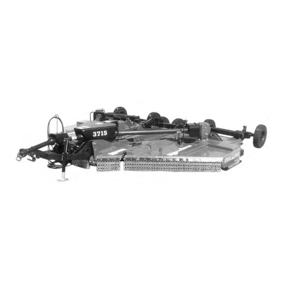
- Page 1 BUSH HOG ® Model 3715/3710 Flex-Wing Rotary Cutter Operator’s Manual OPERATION l l MAINTENANCE 06/09 Rev.1 50029874 $4.00...
- Page 2 If your manual should become lost or destroyed, Bush Hog will be glad to provide you with a new copy. Order from Bush Hog, 2501 Griffin Ave., Selma, Alabama 36703. Most of our man- uals can also be downloaded from our website at www.bushhog.com...
-
Page 3: Table Of Contents
It is the Retail Customer’s responsibility to deliver the product to the authorized Bush Hog Dealer, from whom he purchased it, for service or replacement of defective parts which are cov- ered by warranty. - Page 4 2. If the unit has been subjected to misapplication, abuse, misuse, negligence, fire or other accident. 3. If parts not made or supplied by Bush Hog have been used in connection with the unit, if, in the sole judge- ment of Bush Hog such use affects its performance, stability or reliability.
-
Page 5: Warranty
For Non-Agricultural use, OSHA, ASAE, SAE and ANSI standards require the use of Chain Guards or other protective guards at all times. Bush Hog strongly recommends the use of such guards for Agricul- tural uses as well, to reduce the risk of property damage, serious bodily injury or even death from objects thrown out by or from contact with the cutting blades. -
Page 6: Safety Alert Symbols
Safety Alert Symbol This Safety Alert Symbol means: “ATTENTION! BECOME ALERT! YOUR SAFETY IS INVOLVED!” This symbol is used to call attention to safety precautions that should be followed by the oper- ator to avoid accidents. When you see this sym- bol, carefully read the message that follows and heed its advice. -
Page 7: Safety Precautions
IMPORTANT SAFETY PRECAUTIONS This symbol is used to call attention to safety precautions that should be followed by the op- erator to avoid accidents. When you see this symbol, carefully read the message that follows and heed its advice. Failure to comply with safety precautions could result in serious bod- ily injury. -
Page 8: Federal Laws And Regulations
IMPORTANT FEDERAL LAWS AND REGULATIONS* CONCERNING EMPLOYERS, EMPLOYEES AND OPERATIONS. *(This section is intended to explain in broad terms the concept and effect of the following federal laws and regulations. It is not intended as a legal interpretation of the laws and should not be considered as such). U.S. -
Page 9: Introduction & Description
Each 1-1 INTRODUCTION blade gearbox has two free-swinging uplift blades de- We are pleased to have you as a Bush Hog signed to cut grass, corn stalks and brush. Free- customer. Your Model 3715/3710 Flex Wing Rotary... -
Page 10: Preparation For Use
SECTION II PREPARATION FOR USE 2-1 ATTACHING TO TRACTOR E. Connect hydraulic lines to tractor auxiliary out- let(s). A. IMPORTANT - Adjust tractor drawbar length F. Unpin wing lift cylinders at rod end. Fully ex- to dimension shown in Figure 2-1. Incorrect draw- tend cylinders by pulling on clevis. -
Page 11: Wing Adjustment
Figure 2-3 Linkage Rod Jamnut Turnbuckle 2-4 WING ADJUSTMENT If wings are not level (parallel) from left to right with center deck section, the cutter will windrow and pro- duce an uneven cut. Before first use and periodically thereafter, lower cutter to working position and check for this condition. -
Page 12: Iii.operating Instructions
SECTION III OPERATING INSTRUCTIONS 3-1 GENERAL SAFETY WARNING Only qualified people should operate this machine. Operator should wear hard hat, safety glasses, and IT IS HAZARDOUS TO OPERATE UNIT WITH safety shoes. It is recommended that tractor be WINGS RAISED IN TRANSPORT POSITION. KEEP equipped with Rollover Protective System (ROPS) CLEAR OF MACHINE WHEN RAISING OR LOWER- and a seat belt be used. -
Page 13: Maintenance
Tighten nut to 30 work. Some checks may require raising machine off ft./lbs. Use only genuine Bush Hog replace ground and supporting with blocks. All bolts should ment parts. be torqued as recommended in Torque Chart unless AFTER EACH USE otherwise indicated. - Page 14 40 HOURS 7. Gearboxes - Add EP80W-90 oil, if necessary, 8. Wing Turnbuckles - Apply multi-purpose grease to bring oil level to check plug located on slowly with grease gun. side of housing. Capacity of transfer 120 HOURS gearbox is 2.75 quarts (2.6L). Wing and cen- ter blade gearbox capacity is 6 quarts (5.7L).
-
Page 15: Blade Replacement
A. Remove nuts from blade bolts using 1-11/16” justment is necessary, do so in 1/3 turn incre- socket. (Available from Bush Hog - part no. 6432). ments. Adjust only to provide sufficient torque to B. Inspect blade bolt shoulder for wear. Replace if prevent slippage under normal conditions. - Page 16 BUSH HOG ® MODEL 3715 / 3710 1” x 9-7/8” FLEX-WING ROTARY CUTTER (Model 3710 Illustrated)
- Page 17 1” x 8-5/8” 1” x 12-11/16” 1’ x 7-11/16” 1” x 12-11/16”...
- Page 18 TABLE 4-1 GENERAL TROUBLESHOOTING PROBLEM PROBABLE CAUSE REMEDY Uneven cut Cutter not level side to side or front to rear. Refer to Section II. Worn or bent blades. Replace blades per paragraph 4-3. Stripping or windrowing Possible build up of material under cutter. Clean cutter.
-
Page 19: Assembly
BEFORE OPERATING THE EQUIPMENT, IF YOU HAVE ANY QUESTIONS REGARDING THE PROPER ASSEMBLY OR OPERATION, CONTACT YOUR AUTHORIZED BUSH HOG DEALER OR REPRESENTATIVE. 5-1 MODEL 3715 ASSEMBLY Figure 5-1 Types of Wheels... - Page 20 Hydraulic Cylinder Transport Latch G. There are two types of hitches available for the Model 3715, a 2” ball hitch or a heavy duty, self-lev- eling clevis. 2” Ball Hitch - Install ball hitch weldment into tongue. C. Install axle arm to axle arm mounting bracket Install 5/8”...
- Page 21 H. Connect height adjusting cylinder from cutter Figure 5-11 Wing Cylinder Stop Wing Lugs deck to axle. Secure the cylinder to the axle using 5- 1/8” pin with roll pin and cotter pin. (Figure 5-5) I. Attach hose holder rod to tongue using 5/8” x 2” bolt, nut, flatwasher and lockwasher.
- Page 22 P. Attach driveline retainer ring to the mounting Shield Figure 5-15 bracket welded to the deck of each wing in front of the gearbox input shaft. Secure with two 1/2” x 1-1/2” bolts, lockwashers and hex nuts. (Figure 5-14) Q. Install hinge plate on wing gearboxes using four Bearing 10mm x 25mm bolts, flatwashers and lockwashers Bearing...
-
Page 23: Model 3710 Assembly
REQUIRE THE USE OF CHAIN GUARDS OR IMPROPER SLIP CLUTCH TORQUE SET- OTHER PROTECTIVE GUARDS AT ALL TING. TIMES. BUSH HOG STRONGLY RECOM- MENDS THE USE OF SUCH GUARDS FOR EE. Fold wings into the transport position and install AGRICULTURAL USES WELL, transport lock pins. -
Page 24: Band Installation
OTHER PROTECTIVE GUARDS riage bolts through deck, supports and belting. Se- TIMES. BUSH HOG STRONGLY RECOM- cure with lockwashers and nuts. (Figure 5-22) MENDS THE USE OF SUCH GUARDS FOR C. Tighten all nuts. AGRICULTURAL USES AS WELL, TO RE-... -
Page 25: Hydraulic Diagrams
Center Height Control Cylinder... - Page 26 Center Height Control Cylinder...
-
Page 27: Safety Decals
To promote safe operation, Bush Hog supplies safety decals on all products manufactured. Because damage can occur to safety decals either through shipment, use or reconditioning, Bush Hog will, upon request, provide safety decals for any of our products in the field at no charge. Contact your authorized Bush Hog dealer for more infor- mation. - Page 28 78786 50029418 78608...
-
Page 29: Torque Specifications
TORQUE SPECIFICATIONS Proper toque for American fasteners used on Bush Hog equipment. AMERICAN Recommended Torque in Foot Pounds (Newton Meters).* BOLT DIAMETER Bolt Head Markings WRENCH (IN.) “B” AND SIZE (IN.) “A” THREAD SIZE GRADE 2 GRADE 5 GRADE 8... - Page 30 INSTALLATION OF SPECIAL LOCKING WASHER AND GRADE 5 BOLTS ON THE MODEL 3715 / 3710 AXLE TURNBUCKLE. Refer to the illustrations below for proper locations • Tighten locknuts to 644 ft. lbs +/- 50 ft. lbs. of each component. •...
- Page 32 2501 Griffin Ave., Selma, AL 36703 Telephone (334) 874-2700 www.bushhog.com...
Need help?
Do you have a question about the 3715 and is the answer not in the manual?
Questions and answers