
Related Manuals for Riverside Hydronics TempTrac

Summary of Contents for Riverside Hydronics TempTrac
- Page 1 SERVICE & SETUP MANUAL BOILER ELECTRONIC CONTROLLER Riverside Hydronics, LLC • 3220 Galvez Ave • Fort Worth, Texas 76111 • 800-990-5918 Page 1/ 24 34-81 10/2013...
-
Page 2: Table Of Contents
9. DYNAMIC RESET OF St1 __________________________________________________________ 19 10. WARM WEATHER SHUT DOWN _____________________________________________________ 19 11. HOT KEY PROGRAMMING _________________________________________________________ 20 12. ASSIGNING TEMPTRAC® ADDRESS FOR MODBUS RTU _______________________________ 21 13. ALARMS ________________________________________________________________________ 22 13.1 DIGITAL INPUT ALARMS ______________________________________________________ 23 13.2 AUDIBLE ALARM _____________________________________________________________ 23 13.3 ALARM RECOVERY __________________________________________________________ 24... -
Page 3: Technical Data
TECHNICAL DATA Housing: Self-extinguishing ABS. Case: Facia 100x64 mm; depth 76mm Mounting: Panel mounting in a 56x72 mm panel cut-out with two screws. 3x2mm. Distance between the holes 40mm Protection: IP20. Frontal protection: IP65 with optional frontal gasket mod. RGW-V Connections: Spade on connectors 6.3 mm for supply and relays and 4÷20mA- Screw terminals block for probes, digital input Power supply: 24Vac Class 2... -
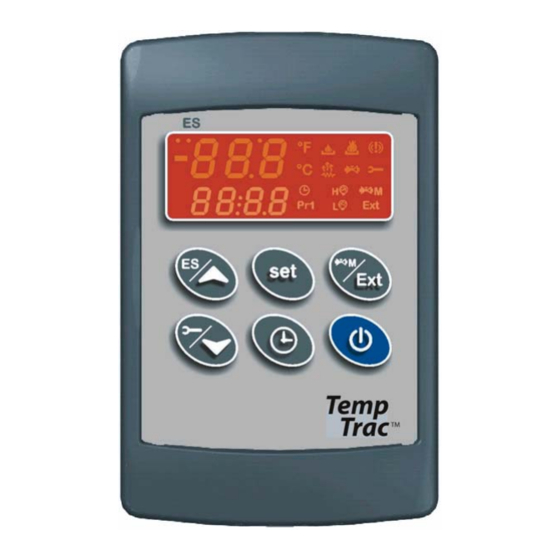
Page 4: Display And Interface
DISPLAY AND INTERFACE UPPER LED READOUT LOWER LED READOUT KEYBOARD Displays and modifies the temperature set points. In programming mode it selects a parameter or confirms an operation. Displays and modifies the energy saving (Night Time Setback) settings. In programming mode it browses the parameter codes or increases the displayed value. Displays the working hours of the load relays. -
Page 5: Led Icon Legend
KEY COMBINATIONS To lock and unlock the keyboard. To enter the programming mode. To exit the programming mode. LED ICON LEGEND LED MODE Function Temperatures are displayed in degrees Fahrenheit. Temperatures are displayed in degrees Celsius. Flashing Output 1 time delay. Output 1 will not energize until AC1 time delay expires OR i3F=Edi and the remote enable/disable is in standby (disabled). -
Page 6: Upper Led Readout (Red)
UPPER LED READOUT (RED) The default display of this readout is the temperature sensed at Probe 2, which is generally the supplied outlet water temperature. Probe 2 may display the tank stored water temperature, flue gas temperature, ambient temperature, remote tank, blended water temperature, etc., depending on the product and application. Refer to your specific product’s Installation and Maintenance Manual and the supplied wiring drawing. -
Page 7: To Set The Energy Savings Time
TO SET THE ENERGY SAVINGS TIME 1. Push the button for more than 3 seconds and the first parameter of the energy saving will be displayed. 2. Use keys to browse them. 3. To change a value push key followed by 4. -
Page 8: Programming
PROGRAMMING SET POINTS PROGRAMMING 1. Push the key, the upper display will show the “St1”, while the lower display will show its value. 2. Use the key to see the set point to be modified. 3. Push the key to modify the displayed value. It starts flashing. 4. -
Page 9: How To Change The Parameter Values In "Pr2
HOW TO CHANGE THE PARAMETER VALUES IN “Pr2” 1. Enter the Programming mode. 2. Select the required parameter with keys. 3. Press the key and the value will start blinking. 4. Use keys to change its value. 5. Press to store the new value and move to the next parameter. To exit: Press or wait 30s without pressing a key. -
Page 10: Parameters
- Pr2: password protected menu. Label: The displayed label when using the Keypad. Range: Indicates the possible values and units that can be set. Firm Version: Firmware of the TempTrac control can be viewed in the rEL parameter. Modbus Modbus... - Page 11 Modbus Modbus Command Firm Range Rev 0.3 Rev 0.5 Address Address Label Version Description X÷Y From X to Y Level Level Base 0 40000+ 0x323 804 Differential for restart working of controller ‐45 ÷ ‐1 °F 0.3 & 0.5 Pr2 Pr2 0.3 & 0.5 DIGITAL INPUTS 0x324 805 Digital input 1 polarity ...
- Page 12 Modbus Modbus Command Firm Range Rev 0.3 Rev 0.5 Address Address Label Version Description X÷Y From X to Y Level Level Base 0 40000+ 0x348 841 Energy saving stop on Thursday 0 ÷ 23h 50 min. ‐ nu 0.3 & 0.5 Pr2 Pr2 0x349 842 Set back temperature on Thursday ‐40÷40°F 0.3 & 0.5 Pr2 Pr2 0x34A 843 Energy saving start on Friday ...
- Page 13 Probe 3 Information/Status Normal=512 or 0x0200, bit (0,1 on) probe 0x105 262 Fault=515 or 0x0203. Fault will buz, Flash Red P3 failure Pr2 0x106 263 Modulation rate output (4 to 20mA) 0÷100% Pr2 0x801 2050 Statas of Relay 1,2&3 bit 0,1,2 0.3 & 0.5 Pr2 Input 3 Alarm, buz, ALMMB, Flashes HP= 4096 or bit # 12 or 13th bit 0xD00 3329 0x0800 Pr2 0xD00 3329 Input 2 Alarm, buz, Flashes LP= 4096 or 0x0800 bit # 12 or 13th bit Pr2 ...
-
Page 14: Relay Outputs
1on=oFF Output 1 is off. c. 1on=on Output 1 is on any time the TempTrac is enabled (Alarms will not disable). On power loss, this contact will be open, and when the TempTrac displays OFF, this will contact will be open. This is no longer a control output, and is not subject to alarms. -
Page 15: Output 2 2Nd Stage (Os2=Std 2On=Reg)
OUTPUT 2 2ND STAGE (oS2=Std 2on=rEG) Kind of action: Heating Reference probe: TP1 Terminals: SPADE 6 & 7 Related Parameters: S2c, St2, Hy2, LS2, US2, AC2, oS2, 2on Probe1 Set2 Set2+ Hy2 time Out2 time NOTES 1. Output 2 will function as an output temperature control when oS2=Std, otherwise output 2 is an alarm output contact. -
Page 16: Output 3 Temperature Protection (3On=Reg)
OUTPUT 3 TEMPERATURE PROTECTION (3on=rEG) Kind of action: Heating Reference probe: TP1 or TP2 Terminals: SPADE 8 & 9 Related Parameters: S3c, St3, Hy3, LS3, uS3, AC3, 3on, o3P Probe2 Set3 Set3+ Hy3 time Out3 time NOTES 1. Output 3 can be used to enable pumps when temperature falls below a St3. 2. -
Page 17: Output 3 Alternate Set Point
OUTPUT 3 ALTERNATE SET POINT Kind of action: Heating Reference probe: TP1 or TP2 Related Parameters: St3, Hy3, LS3, US3, AC3, St5, Hy5, 3on, o3P, SSE, AC5, ACA NOTES 1. When SSE is enabled and Output 1 is in a de-energized state (off) Output 3 will function according to St3. When Output 1 is in an energized state Output 3 will function according to St5. -
Page 18: Modulation Output
MODULATION OUTPUT Kind of action: if Sr< 0 Heating; if Sr>0 Cooling. See diagrams. Current Current Sr < 0 Sr > 0 (mA) (mA) Set4 Set4 + Sr Set4 + Sr Temper. Set4 Temper. Reference probe: TP1 Related Parameters: S4c, St4, Sr, PS4, PP4, Ac4, i1S, i1t, i1F, i1d NOTES 1. -
Page 19: Modulation Buffer
MODULATION BUFFER Probe 2 Th4+HY4 20ma Out 4 Time Kind of action: Heating Reference probe: TP2 Related Parameters: Th4, HY4 NOTES 1. This function references probe TP2 and will trigger output 4 to reduce the signal to 4mA when the temperature of Th4 is reached by TP2 and hold it until TP2 drops below TH4+HY4. -
Page 20: Hot Key Programming
11. HOT KEY PROGRAMMING To upload program from control to HOT KEY: Insert HOT KEY into the TTL/HOT KEY connection on the back of the control. Press keys together momentarily then press the key. The uPL message will appear while uploading is occurring and the End message will appear when finished. -
Page 21: Assigning Temptrac® Address For Modbus Rtu
Each TempTrac on a RS-485 network must have a different address, to enable proper communication. NOTE: The default for each TempTrac is Address #1. You can assign them to any number in the range of 1-247, this is the limitations of the MODBUS-RTU standard. -
Page 22: Alarms
13. ALARMS Alarm messages are displayed in the lower display of the TempTrac and are alternated with the default message. These alarm messages are displayed together with the icon devoted to signalling the alarm conditions. Message Cause Outputs and information Audible alarm sounds. -
Page 23: Digital Input Alarms
The Instrument will revert to normal operation when these digital inputs are disabled + any button is pressed. 13.2 AUDIBLE ALARM The TempTrac audible alarm is activated each time a connected alarm condition occurs. The following are representative alarm conditions that may be connected to and activate the TempTrac audible alarm (some alarms may be connected to and operate separately from the TempTrac on some products). -
Page 24: Alarm Recovery
4. The digital input 2 & 3 alarms recover when condition(s) listed above are normalized and any button is pressed. 5. RTC alarm stops after programming the real time clock. 6. RTF alarm requires the replacement of the TempTrac® device. For additional information, contact the Riverside Hydronics Customer Service department at 800-990-5918.
Need help?
Do you have a question about the TempTrac and is the answer not in the manual?
Questions and answers