
Related Manuals for Riverside Hydronics TempTrac

Summary of Contents for Riverside Hydronics TempTrac
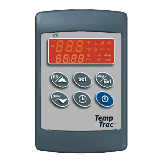
- Page 1 BOILER ELECTRONIC CONTROLLER USER MANUAL UPPER LED READOUT LED ICONS LOWER LED READOUT Riverside Hydronics LLC • 3220 Galvez Dr • Fort Worth, Texas 7611 • 800-990-5918 Page 1 / 7 34-80 04/2013...
- Page 2 DISPLAY AND INTERFACE KEYBOARD BUTTONS Displays and modifies the temperature set points. In programming mode, it selects a parameter or confirms an operation. Displays and modifies the energy saving (Night Time setback) settings. In programming mode, it browses the parameter codes or increases a displayed value. Displays the working hours of the load relays.
- Page 3 UPPER LED READOUT The default display of this readout is the temperature sensed at Probe 2, which is generally the supplied outlet water temperature. Probe 2 may display the tank stored water temperature, flue gas temperature, ambient temperature, remote tank or blended water temperature, etc., depending on the product and application. Refer to your specific product’s Installation and Maintenance Manual and the supplied wiring drawing.
- Page 4 4. To exit push or wait 15 seconds without pressing any buttons. Note: This device recognizes Sunday as the first day of the week and Saturday as the last. TO SET THE ENERGY SAVING TIME (NIGHTIME SETBACK) 1. Push and hold the button for more than 3 seconds and the first parameter of the energy saving will be displayed.
- Page 5 To program different set points proceed as described below: 1. Press the button, the Upper LED readout will display the “St1” parameter name, while the Lower LED readout will show the corresponding value. 2. Use the buttons to cycle the Upper LED readout through the St1, St2 and St3 parameter names. On some products St2 and St3 will be located in the PR2 menu and require password access.
- Page 6 8. Each boiler should be assigned a different address in order for proper communication to occur. Note: The default for each TempTrac is Address #1. You can assign them to any number in the range of 1-247, this is the limitations of the MODBUS RTU standard.
- Page 7 The TempTrac audible alarm is activated each time a connected alarm condition occurs. The following are representative alarm conditions that may be connected to and activate the TempTrac audible alarm (some alarms may be connected to and operate separately from the TempTrac on some products).
Need help?
Do you have a question about the TempTrac and is the answer not in the manual?
Questions and answers