Table of Contents
Advertisement
Available languages
Available languages
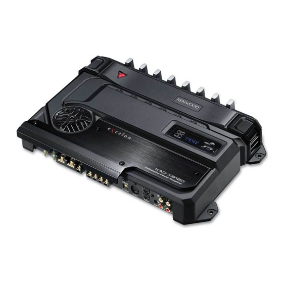
KAC-X812D
SUBWOOFER POWER AMPLIFIER 7 page 2-9
INSTRUCTION MANUAL
AMPLIFICATEUR DE PUISSANCE DU SUBWOOFER 7 page 10-17
MODE D'EMPLOI
AMPLIFICADOR DE POTENCIA DEL ALTAVOZ DE SONIDO ENVOLVENTE 7 página 18-25
MANUAL DE INSTRUCCIONES
Take the time to read through this instruction manual. Familiarity
with installation and operation procedures will help you obtain the
best performance from your new power amplifier.
For your records
Record the serial number, found on the back of the unit, in the spaces
designated on the warranty card, and in the space provided below. Refer
to the model and serial numbers whenever you call upon your Kenwood
dealer for information or service on the product.
Model KAC-X812D Serial number
US Residence Only
Register your Kenwood product at
www.kenwoodusa.com
© B64-3393-00/00 (KV)
Register Online
Advertisement
Table of Contents

Related Manuals for Kenwood KAC-X812D


Summary of Contents for Kenwood KAC-X812D
- Page 1 Record the serial number, found on the back of the unit, in the spaces designated on the warranty card, and in the space provided below. Refer to the model and serial numbers whenever you call upon your Kenwood dealer for information or service on the product.
-
Page 2: Safety Precautions
NOTE • If you experience problems during installation, consult your Kenwood dealer. • If the unit does not seem to be working right, consult your Kenwood dealer. NOTE This Class B digital apparatus complies with Canadian ICES-003. -
Page 3: Installation Procedure
2. Set the unit according to the intended usage. Hexagon Wrench 3. Connect the input and output wires of the units. 4. Connect the speaker wires. 5. Connect the power wire, power control wire and grounding wire following this order. - Page 4 • Connect the speaker wires to appropriate speaker connectors separately. Sharing the negative wire of the speaker or grounding speaker wires to the metal body of the car can cause this unit to fail. • After installation, check that the brake lamps, winkers, and wipers work properly.
-
Page 5: Power Indicator
Amplifier control is possible even while OFF. ^ PHASE switch When this switch is set "180°" (Reverse) the speaker output phase is reversed. & BRF (band reject filter) switch When this switch is set to "-6dB"/"-12dB", frequencies in the band set with the "B.R.F. -
Page 6: Display Mode
Amplifier Control System Display mode You can set up the display items as follows: Enter Menu mode Press the [MENU] button. "VOLT"/"CURR"/"TEMP"/"FAN" is displayed. Select a display item Press the [2] or [3] button. The display items are switched in the following sequence. Display Information "VOLT"... - Page 7 "AMP × E-02"/"AMP × COND E-02" NOTE Turn the POWER switch Off and release the protection. If the error message continues, consult to the Kenwood’s dealership. When the speaker cord is shorted. "AMP × E-03"/"AMP × COND E-03" When the speaker output is in contact with the vehicle ground.
-
Page 8: Troubleshooting Guide
• The speakers wire are connected with wrong 9 / · polarity. The sound quality is bad. (The sound is distorted.) • A speaker wire is pinched by a screw in the car body. • The switches may be set improperly. The sound does not change •... -
Page 9: Specifications
Specifications Specifications subject to change without notice. Audio Section Max Power Output ... 1600 W Rated Power Output (+B = 12.0 V) (4 Ω) (20 Hz – 200 Hz, 0.5 % THD) ... 300 W × 1 (2 Ω) (100 Hz, 0.5 % THD) ... 600 W × 1 Rated Power Output (+B = 14.4 V) (4 Ω) (20 Hz –... -
Page 10: Précautions De Sécurité
Unités de commande disponibles : Une unité centrale compatible Kenwood LX-Bus commercialisée en 2004 ou plus tard peut commander cette unité. Le fonctionnement de la commande (LX) AMP est expliqué dans le mode d’emploi de l’unité centrale. - Page 11 Installation 386 mm 372 mm LPF OPERATION 200 Hz 150 Hz 100 Hz 70 Hz 50 Hz 50 60 300 400 (Hz) Vis d’assemblage à Conduit six pans creux (M4 × 8 mm) Ventilateur de refroidissement Couvercle Tableau d'installation, etc. (épaisseur: 15 mm ou plus) Accessoires Vis taraudeuses...
- Page 12 • Après l’installation, vérifier que les voyants de frein, les clignotants et les essuie-glace fonctionnent correctement. ■ Connexion LX-Bus Vers changeur de disque Kenwood/ Accessoire externe en option Unité centrale Câble de commande de l’alimentation Amplificateur maître "0"...
- Page 13 Commande l’unité d’alimentation. Assurez-vous de le connecter à l’ensemble des différents systèmes. 5 Bornes SPEAKER OUTPUT Cet appareil étant conçu pour fonctionner avec une impédance de charge de 1 Ohm, tout haut-parleur dont l'impédance est égale ou supérieure à 1 Ohm peut être branché...
- Page 14 Système de commande d’amplificateur Mode d’affichage Vous pouvez régler les éléments de l’affichage comme suit : Entrer dans le mode menu Appuyez sur la touche [MENU]. "VOLT"/"CURR"/"TEMP"/"FAN" est affiché. Sélectionner un élément de l’affichage Appuyez sur la touche [2] ou [3]. Les éléments de l’affichage sont commutés dans l’ordre suivant.
- Page 15 "AMP × E-02"/"AMP × COND E-02" REMARQUE Eteignez le commutateur POWER et débloquez la protection. Si le message d’ e rreur persiste, consultez votre revendeur Kenwood. Lorsque le cordon du haut-parleur est en court-circuit. "AMP × E-03"/"AMP × COND E-03"...
-
Page 16: Guide De Depannage
Filtre coupe bande (B.R.F.) Pour certaines fréquences, les caractéristiques de l'habitacle du véhicule sont telles que des résonances parasites et des ondes stationnaires peuvent prendre naissance. En n'éliminant que les fréquences responsables des résonances et des ondes stationnaires, le filtre coupe-bande peut supprimer ces phénomènes gênants sans altérer de façon significative la qualité... -
Page 17: Spécifications
Spécifications Les spécifications sont sujettes à modifications sans préavis. Section audio Puissance de sortie max..1600 W Puissance de sortie norminale (+B = 12,0 V) (4 Ω) (20 Hz – 200 Hz, 0,5 % THD) ... 300 W × 1 (2 Ω) (100 Hz, 0,5 % THD) ... -
Page 18: Precauciones De Seguridad
Unidades de control disponibles: La unidad central de soporte LX-Bus de Kenwood puesta en venta en 2004 o posteriormente puede controlar esta unidad. Las operaciones del control del AMP (LX) en el manual de funcionamiento de la unidad central. -
Page 19: Vista Exterior
Instalación 386 mm 372 mm LPF OPERATION 200 Hz 150 Hz 100 Hz 70 Hz 50 Hz 50 60 300 400 (Hz) Tornillo de cabeza Conducto hexagonal (M4 × 8 mm) Ventilador de refrigeración Tapa Tablero de instalación, etc. (grosor: 15 mm o más) Accesorios Tornillo autorroscantes (ø5 ×... - Page 20 • Después de la instalación, compruebe que las lámparas del freno, luces de destello y limpiaparabrisas funcionar correctamente. ■ Conexión LX-Bus Al cambiador de discos Kenwood/ Accesorio opcional externo APARATO CENTRAL Cable de control de potencia Amplificador principal "0"...
- Page 21 Controla la potencia de la unidad. Asegúrese de conectarlo con todos los sistemas. 5 Terminales SPEAKER OUTPUT Como este aparto acepta altavoces con una impedancia mínima de 1 ohmio, conecte altavoces con una impedancia de 1 ohmio o más a estos terminales.
- Page 22 Sistema de control del amplificador Modo de visualización Es posible configurar los elementos de ajuste de la siguiente manera: Acceda al modo de menú Pulse el botón [MENU]. Se visualiza "VOLT"/"CURR"/"TEMP"/"FAN". Seleccione un elemento de visualización. Pulse el botón [2] o [3]. Los elementos de visualización cambian en la frecuencia siguiente.
- Page 23 "AMP × E-02"/"AMP × COND E-02" NOTA Desactive el interruptor POWER y libere la protección. Si el mensaje de error continua, consulte al distribuidor Kenwood. Cuando el cable del altavoz está en corto. "AMP × E-03"/"AMP × COND E-03" Cuando la salida del altavoz hace contacto con la masa del vehículo.
-
Page 24: Guia Sobre Localización De Averias
Filtro de rechazo de banda (B.R.F.) Las propiedades acústicas del compartimiento del vehículo tienden a causar oscilaciones debido a la resonancia o falta de claridad del sonido causada por las ondas estacionarias en ciertas frecuencias. El filtro de rechazo de banda puede resolver los problemas de resonancia o sonido poco claro causando una influencia mínima en la calidad del sonido, porque sólo elimina las frecuencias que causan la resonancia o las ondas estacionarias. -
Page 25: Especificaciones
Especificaciones Especificaciones sujetas a cambios sin previo aviso. Sección de audio Máxima potencia de salida ... 1600 W Salida de potencia nominal (+B = 12,0 V) (4 Ω) (20 Hz – 200 Hz, 0,5 % de distorsión armónica total) ... 300 W × 1 (2 Ω) (100 Hz, 0,5 % de distorsión armónica total) ...
Need help?
Do you have a question about the KAC-X812D and is the answer not in the manual?
Questions and answers