Table of Contents
Advertisement
Advertisement
Chapters
Table of Contents

Subscribe to Our Youtube Channel
Related Manuals for ABM International LA-763


Summary of Contents for ABM International LA-763
- Page 3 LA-763: V1.1 TABLE OF CONTENTS: Introduction Section 1.0 – Safety Section 2.0 - Machine Setup Section 3.0 – Machine Operation Section 4.0 – Troubleshooting guide and notebook Section 5.0 – Parts List Figure 0.1 – LA-763...
- Page 4 LA-763: V1.1 Introduction ABM International would like to thank you for the purchase of an LA-763 Long Arm Sewing Machine. ABM is confident that this machine will meet or exceed your expectations for cost, speed and durability. If at anytime you experience problems with any of your ABM machines we ask that you contact us - 24 hours a day by calling our service department at (281) 443-4440.
- Page 5 4. Wear appropriate personal safety protection. 5. Stop the LA-763 immediately at any sign of malfunction or danger. 6. Do not crawl under or into the LA-763 for any reason during the operation of the machine. 7. Do not reach into the LA-763 at any time during the operation of the machine.
- Page 6 LA-763: V1.1 11. Before starting the LA-763, ensure that no loose tools, bars or parts are lying in or on any part of the machine. 12. Proper fire fighting equipment should be kept in good operating condition and kept near in the event of fire.
- Page 7 LA-763: V1.1 SECTION 2.0 – Machine Setup The LA-763 ships fully tested ready to operate. As a result, this manual provides a section on machine setup so that you can install the machine. Please read this manual in its’ entirety and follow all ABM instructions, especially the inspections. Total setup time, less power and air hook-up, should take approximately 1 hour.
- Page 8 LA-763: V1.1 Figure 2.0 – Electrical Panel. FINAL TEST: WARNING – WHEN OPERATING THE MACHINE, YOU MUST ENSURE THAT THERE ARE NO LOOSE ITEMS SUCH AS TOOLS FOOD DRINKS ETC. ON THE MACHINE AND THAT ALL PESONNEL ARE CLEAR OF THE...
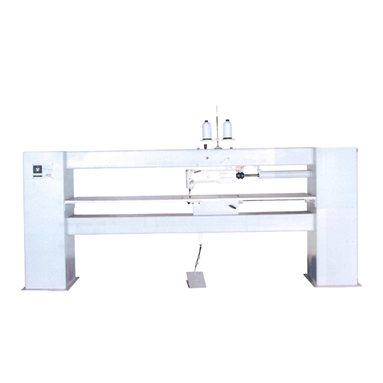
- Page 9 LA-763: V1.1 Figure 2.1 – LA-763 sewing head. Inspect the front of the machine and ensure that the sewhead is free of obstructions. Step 1: Depress the treddle forward and the sewhead will begin to run. Step 2: Release the treddle and the needle will stay down to pivot your fabric.
- Page 10 This section will discuss how to properly use the LA763 to fulfill all of your sewing needs. The LA-763 is equipped with either a mechanical or pneumatic foot lifter to create clearance under the foot when inserting and removing your product to be sewn.
- Page 11 LA-763: V1.1 Operating the LA-763 is a simple task. Turn the main power on and allow the machine to energize (this may take 5 seconds). While the machine is powered on please make sure that the foot pedal is not being pressed or the machine will activate an electrical safety measure that will not allow the sewhead to work.
- Page 12 LA-763: V1.1 Speed can also be limited on the servo controller interface. Press the TE SPEED button until the menu with speed is shown. Press the four lower arrow keys to increase or decrease the desired maximum speed. When modification is complete, press TE SPEED to store the number in memory.
- Page 13 LA-763: V1.1 SECTION 4.0 – Troubleshooting guide ABM has done its best to include as much information as possible. However, not all problems are listed, therefore ABM asks that whenever a problem occurs you contact a service technician at our home office. To reach service dial 281-443-4440 and ask for a service technician, they are on call 24 hours a day, seven days a week.
- Page 14 LA-763: V1.1 TROUBLESHOOTING NOTES: Date Problem Solution...
- Page 15 LA-763: V1.1 TROUBLESHOOTING NOTES: Date Problem Solution...
- Page 16 LA-763M Long Arm machine manual: Electric versions www.abminternational.com Installation instructions Operational guide Troubleshooting guide Parts list...
- Page 17 Table of Contents Section 1.0 - Machine Operation Guide Section 2.0 - Troubleshooting guide Section 3.0 - Parts List...
-
Page 18: Instruction Manual
EcoDrive QE3760/QE5540 Instruction Manual Part 1 QUICK-ROTAN Elektromotoren GmbH Königstraße 154 67655 Kaiserslautern Tel: 0631 / 200 38 80 Fax: 0631 / 200 38 62 E-Mail: tech.supp@quick-rotan.com www.quick-rotan.com English 2004-03-10... - Page 19 symbol confirms that the respective drive system meets the applicable safety requirements of the following EU directives: - EC Maschine Directive 89/392/EWG - EMV Directive 89/336/EWG - Low Voltage Directive 73/23/EWG ed-1-en 04-03-10...
-
Page 20: Table Of Contents
Contents Page Part 1 General Safety Information 1.1 - 1.2 Technical Specifications 2.1 - 2.3 Range of Application Scope of Supply Transport and Storage Mounting Instructions 6.1 - 6.7 Mounting of the Motor Adjustment of the motor and machine Electrical connection Preventive Action Against Electrostatic Charges Mounting of Speed Control Unit (SWG) Part 2... -
Page 21: General Safety Information
General Safety Information This EcoDrive Sewing Drive System has been constructed and tested in compliance with the relevant regulations and safety standards and has left our factory in proper safety condition. In order to maintain this condition and to ensure non-hazardous operation, the user is obliged to observe the information and warning notes contained in this Operating Instructions Manual. - Page 22 Do not introduce or drop any objects, such as needles, into the ventilation louvers. Keep your hands out of the area of moving parts! Do not operate the EcoDrive when using aerosols (sprays) or oxygen! This Operating Instructions Manual is an integral part of the EcoDrive and must be passed on with it in case of change of ownership.
-
Page 23: Technical Specifications
Technical Specifications Rated Values: ED QE3760 EDL QE5540 Voltage (U N) [V] 230, single phase AC Frequency (f N) [cps] 50/60 Current (drive system) (I N) [A] Current (control system) [A] Power (output) (P 2 ) [W] Speed (n n ) [1/min] 6000 4000 Torque (M n ) [Nm]... - Page 24 Dimensions of the Control System (small version) ED 350,4 290,4 350,4 350,4 Control System (broad version) EDx 350,4 290,4 290,4 290,4 ed-1-en 04-03-10...
- Page 25 Motor l 1 = l 2 = 147,5 187,5 ed-1-en 04-03-10...
-
Page 26: Range Of Application
3. Range of Application The EcoDrive is not a ready-to use machine, but is intended for installation into other machines, such as sewing units and sewing equipment used by the sewing thread processing industry. The EcoDrive is destined for use in clean and dry localities. Any application or use beyond the conditions stipulated above, such as outdoors, in moist or explosion- hazardous environment, is not considered to be in compliance with specifications. -
Page 27: Mounting Instructions 6.1
6. Mounting Instructions Before starting installation, please remove all parts from the packing material. The carton holds the EcoDrive, accessories and Operating Instruction manual. Check the content if complete. If you have any questions with the installation, not clarified through the Instruction Manual, please contact us or one of our nearest Service Stations. - Page 28 6.2 Motor and machine adjustment Adjust motor shaft to reference position (zero position) - Terminal box at top (viewpoint) - Motor shaft groove (-90° ) quarter to twelve in re lation to terminal box equals zero position, rotate motor shaft. Adjust machine reference position (zero position) - Rotate machine pulley (sewing rotation) until needle point starts penetrating needle hole of throat plate (zero position)
-
Page 29: Electrical Connection
6.3 Electrical Connection (to Mains Power) All work on the electrical equipment (connection, maintenance, repair) is permitted to be performed only by or under the supervision of a properly qualified technician. The EcoDrive is designed for connection to an earthed AC mains power system having a rated voltage between 190 and 240 Volts, 50/60 cps. - Page 30 The following applies to TT and IT systems: All elements protected by a common protective device must be connected to the same earthing via protection earth conductors. All elements apt to be touched simultaneously must be connected to a common earthing. The following applies additionally to IT systems: No active conductor within the installation is permitted to be earthed directly.
- Page 31 It is not permitted to disable the protection system by using extension cables not equipped with a protection earth conductor. Caution: Any interruption of the protection earth conductor within the EcoDrive or outside, or by disconnecting the protection earth connection, can result in making the equipment hazardous.
- Page 32 6.4 Electro-Magnetic Compatibility (EMC) The EcoDrive is designed for installation/attachment to EMC sewing units and equipment, i.e. it complies with the relevant EMC regulations (CDV IEC 204-3-1 44 sec 169) for a cable length of 500 mm at each input or output connector. In accordance with experience, this is adequate for sewing units. More complicated sewing equipment may require additional action due to longer cables, unfavourable cable placement, neighbouring strong interference fields etc.
-
Page 33: Mounting Of Speed Control Unit (Swg)
6.5 Mounting of the Speed Control Unit (SWG) Attach the speed control unit by means of the mounting bracket under the machine table. Connect the push/pull bar of the SWG with the machine treadle by means of a pitman rod. Install the mounting bracket for the SWG in such a way that the pitman rod and the push/pull bar of the speed control unit (SWG) line up to the treadle. - Page 34 EcoDrive QE3760/QE5540 Type P40ED Instruction Manual Part 2 QUICK-ROTAN Elektromotoren GmbH Königstraße 154 67655 Kaiserslautern Tel: 0631 / 200 38 80 Fax: 0631 / 200 38 62 E-Mail: tech.supp@quick-rotan.com www.quick-rotan.com Englisch 2004-03-08...
- Page 35 List of Contents Part 2 Chapt. Contents Page Description of the EcoDrive drive system 7.1 - 7.5 Motor QE3760 / QE5540 Control system Speed control unit SWG2 Control panel S1 Application 8.1 - 8.4 Entering the start and end backtacks Sewing Darning program Counted seam...
-
Page 36: Description Of The Ecodrive Drive System 7.1
7. Description of the EcoDrive Drive System The EcoDrive Drive System is an electronically commutated, brushless DC motor. The system is composed of the following subassemblies Fig.7.2 Fig.7.1 3 3 3 3 3 3 3 3 3 3 3 3 3 3 3 3 3 3 3 3 Fig.7.4 Fig.7.5 Fig.7.3... - Page 37 7.2 Control system Fig. 7.6 Fig 7.7 The control box is attached to the underside of the machine table by means of the four enclosed screws. The mains connection is single-phase, using the three-wire cord protruding from the rear and a standard safety plug.
- Page 38 7.3 Encoder SWG2 the SWG2 is attached under the table with the provided bracket and mechanically connected with the pedal of the machine with the provided linkage. Electrical connection of the SWG2 is made with the nin-pin coupling on plug X3 on the rear side of the control.
-
Page 39: Screen Displays
7.4 Control panel The control panel (Fig. 7.8) consists of display 1 and the function keys described below. The display 1 consists of a single-line, 7 segment LCD display with 8 symbols. The texts 2, located above and next to the LCD display, show the respective status of the function keys and the operating status of the machine. - Page 40 Start backtacks If this key is pressed, the backtacks at the beginning of the seam (start backtacks) are switched on or off. The number of forward stitches (A) or reverse stitches (B) for the start backtacks can be changed by pressing the +/- key underneath. To convert from double backtack to single backtack set the number of stitches for the corresponding seam section at zero.
-
Page 41: Application 8.1
Application This EcoDrive drive can be used with the external operator’s control panel S1. Switching on The on/off switch (mains switch) is located under the sewing machine table. When activated and live, an control lamp at the switch lit up. Maximum speed The maximum speed can be adjusted with the control panel S1. -
Page 42: Sewing
8.2 Sewing In the sewing mode all relevant settings for the sewing operation are displayed. Functions can be switched on or off by pressing a key. Values for start and end backtacks or stitch placement can be changed directly. When the machine is switched on, the sewing mode is always activated. Switch on the machine. -
Page 43: Darning Program
8.3 Darning program 1 5 1 5 The corresponding function can be switched on or off directly with the Darning program key. The "counted seam" function is switched off automatically. Several darning programs with different seam sections A and B can be selected. The number of required darning programs can be selected by operating the +/- key 1. -
Page 44: Error Messages
8.5 Error messages If a fault occurs, the text "ERROR" appears on the display, together with an error code and short instructions. An error message is caused by incorrect settings, faulty elements or seam programs as well as by overload conditions. For an explanation of the error codes see Chapter 9. -
Page 45: Error Codes (Malfunction Diagnostics) 9.1
Error Codes (Malfunction Diagnostics) The control system of the drive cyclically tests its own functional condition and the functional condition of the complete drive system. Malfunctions are signalled via the display of the external control panel, for instance: ERROR Summary of the malfunctions: Malfunction-No. - Page 46 Malfunction-No. Reason Remedy Power electronics shut-off Eliminate cause. when motor runs why: a) Overcurrent, short circuit in motor or supply line b) Overvoltage, mains voltage too high (>300 V), motor overloaded while decelerating c) Undervoltage Machine blocked, no increment from Eliminate cause.
-
Page 47: Parameter Settings
9.1 Parameter settings 9.1.1 Selecting the user level Switch on the machine. Press the TE/Speed key twice to call up the input mode. 1 0 1 By pressing the corresponding +/- key select the parameter group "798". 7 9 8 By pressing the corresponding +/- key select the desired user level: "0"... -
Page 48: Example Of A Parameter Input
9.1.2 Example of a parameter input Switch on the machine. Press the TE/Speed key twice to select the input mode. 1 0 1 By pressing the corresponding +/- key select parameter "798" and the user level "B", see Chapter 9.1.1 Selecting the user level. 7 9 8 Select parameter "607"... -
Page 49: Reset / Cold Start
Reset / Cold start After selecting the reset menu, by pressing the corresponding key it is possible to reset seam parameters, reset seam programs and to execute a cold start. Press and hold "+" on keys A and D and switch on the machine! Resetting the seam parameters Press "+"on key "A". -
Page 50: Start Of Operation 10.1
Start of operation If the EcoDrive has been stored at a temperature of <+5° C, then a working temperature of between +5° C and +40° C must first be obtained. The equipment must be dry. Before work with the machine can be started, make sure to perform the following: a) Control the direction of rotation and the reference position of the needle bar b) Control the needle positions c) Control the maximum speed... -
Page 51: Control Of The Maximum Speed
The position can again be corrected. When no further correction is needed, then proceed as with g) below. g) As soon as another parameter number is called up, e.g. example 703, the previously programmed value of <702> is memorized. h) With parameter 703 correction is obtained as described above for parameter 702. Deactivate programming level „b“... -
Page 52: Hardware Test
10.4 Hardware Test Hardware Test is a check routine permitting to use the control panel S1 for testing various components of the drive system (control system) and of the machine installation. Activation of the „HARDWARE TEST“ = „HW-Test“ routine push key TE-SPEED two times to activate programming level „c“... - Page 53 To call up various functional elements within a test block such as advancing from an Input to the next, use key field 2 +/- on the control panel S1. To activate functional elements selected, use key field 4 +/- on the control panel S1. Input Input no.
- Page 54 The designations A (for output) are located on the lefthand side of the connectors shown. The solenoids/solenoid valves assigned to the outputs are designated Y in the connections diagram and have the same numbers as the associated outputs, i.e. solenoid Y2 is connected to output A2 solenoid Y3 is connected to output A3 solenoid Yx is connected to output Ax The operating state of the output displayed is signalled in the 7th digit of the display.
- Page 55 EcoDrive QE3760/QE5540 Type P40ED Instruction Manual Part 3 QUICK-ROTAN Elektromotoren GmbH Königstraße 154 67655 Kaiserslautern Tel: 0631 / 200 38 80 Fax: 0631 / 200 38 62 E-Mail: tech.supp@Quick-Rotan.com www.quick-rotan.com Englisch 2005-10-25...
- Page 56 List of Contents Part 3 Chapt. Contents Page Survey and List of Parameters 11.1 - 11.9 11.1 Explanation of Parameter Survey 11.2 Explanation of Parameter List 11.3 Parameter Survey 11.4 List of Parameters Electrical Connections Diagram 12.1 - 12.4 Appendix adaptor cable 12.5 Technical updatings reserved! p-40-ed-3-en...
- Page 57 11. Survey and List of Parameters 11.1 Explanation of Parameter Survey The parameter survey is designed as an aid for finding parameters quickly. It is a summary of references for the parameter list. Listed behind each reference are all parameters which exert an influence on the function described by the reference.
- Page 58 11.3 Parameter survey P40ED 1_040_10 (PARAM.ENO) Function Abbrev’n Parameter Input Connection Output Socket/Contacts Accelerate DRZAN Backtack 105/107/110 364/391/523 584/585 Backtack inversion Backtack suppression RIUNT Blower Brake DRZAB Catcher FANG Chopper MESSER 105/110 Control 880/884/885 886/887/889 890/900 Decorative backtack ZRIE 391/522/523 530/775 Defect search Delay...
- Page 59 Needle position change-over 446/748 Needle up without trimming NHOS 446/710/748 Number of stitches STZA 111/112/470 ON period EINZ 528/715/889 Operator panel Photocell 111/112/113 163/199/615 Presser foot 356/636/642 651/719/729 730/770 Program 203/206/311 Programming level C Residual brake STBR Seam end 110/206 Seam start Single stitch 392/446/748...
- Page 60 Thread monitor 382/660/760 Thread puller Thread tension release 393/538/636 707/761 Thread trimming 311/609/646 705/706/734 Thread wiper 668/715 Time needed to switch on EINZ 528/715/889 Timing output 538/642/643 705/719/721 Vacuum SAUG 105/110/356 Zigzag machine p-40-ed-3-en 11.4 05-10-25...
- Page 61 11.4 List of Parameters P40ED 1_040_10 (PARAM.EN) Function (Meaning) Level Range Standard Values Value (BDF) Audible signal of the control panel pushbutton A,B,C Kl. 1, 2, 3, 4 1 = on 0 = off (AR/RIE/DRZ/MESSER/NA/SAUG/STVD) Speed for B,C 0300 - 2000 1200 Kl. 1, 3, 4 front backtack/ stitch condensation 0300 - 2000 700 Kl.
- Page 62 (ZRIE/RIE) single stitch-decorative backtack 0200 - 0700 450 Kl. 4 1 = on Kl. 1, 2, 3 0 = off (EST) Change-over to sinle stitch via treadle Kl. 4 1 = on Kl. 1, 2, 3 0 = off (FSL) Thread tension release after seam end Kl.
- Page 63 (PF/VERZ/TA) preser foot time from switch-on 0010 - 0150 100 Kl. 1, 2, 3, 4 to voltage reduction (cycling) (TUM/VERZ/TA) feed reverse time from switch-on 0010 - 0150 100 Kl. 1, 2, 3, 4 to voltage reduction (cycling) (SN) Without thread trimmer magnet at seam end Kl.
- Page 64 (NHOS/NPW/EST/RIV/RIUNT/NAPO) Input E3 is 0001 - 0007 5 Kl. 1, 2, 3, 4 1 = needle up without trimming 2 = needle position change-over 3 = single stitch 4 = single stitch with reduced length 5 = backtack inversion 6 = backtack suppression 7 = change-over position 8 = puller lift switched off (TUM) Feed reverse speed of reaction (40, 50,...
- Page 65 (REG) Additional P-Amplification of the speed 0001 - 0024 10 Kl. 1 control 0001 - 0030 16 Kl. 2, 3 0001 - 0024 6 Kl. 4 (DRZ/SN) Trimming release speed 0030 - 0500 300 Kl. 1, 2, 3, 4 (ANZ) Display change-over Kl.
- Page 66 12. Electrical Connections Diagram X5 P40ED [A3] [A2] +15V +24V 500 mA 500 mA 500 mA 500 mA 500 mA 500 mA +24V 500 mA 500 mA [A10] +24V P40ED12 12.1 05-10-25...
- Page 67 Bedeutung der Magnete bzw. Magnetventile, Taster / Meaning of magnets and/or solenoids and keys Signification des aimants resp. solenoides et touches / Significação dos imaõs e/ou as solenoidas e teclas Significato dei magneti, delle valvole magnetiche e dei tasti / Significación de los imanes y/o los solenoides y pulsadores / Betekenis van de magneten resp.
- Page 68 Bedeutung der Magnete bzw. Magnetventile, Taster / Meaning of magnets and/or solenoids and keys Signification des aimants resp. solenoides et touches / Significação dos imaõs e/ou as solenoidas e teclas Significato dei magneti, delle valvole magnetiche e dei tasti / Significación de los imanes y/o los solenoides y pulsadores / Betekenis van de magneten resp.
- Page 69 Bedeutung der Magnete bzw. Magnetventile, Taster / Meaning of magnets and/or solenoids and keys Signification des aimants resp. solenoides et touches / Significação dos imaõs e/ou as solenoidas e teclas Significato dei magneti, delle valvole magnetiche e dei tasti / Significación de los imanes y/o los solenoides y pulsadores / Betekenis van de magneten resp.
- Page 70 Appendix adaptor cable Important Notice! Your newly purchased EcoDrive control system is designed to be connected to a sewing machine/system via connector X5. This connector X5 is a 37 pole sub-d jack as shown in the wiring diagram. The connections/wiring of X5 is not identical nor compatible with the connections of the same type of jack X5 of the Ministop control box, nor with the same type of 37 pole sub-d jack of a Servo control box! In order to avoid damage to the control box, you may only connect the EcoDrive to...
Need help?
Do you have a question about the LA-763 and is the answer not in the manual?
Questions and answers