
Related Manuals for ClearPix CFB12DN-H2

Summary of Contents for ClearPix CFB12DN-H2
-
Page 1: Installation Guide
Installation Guide ClearPix High Definition H.264 IP Cameras: CFB12DN-H2, FB12DN-H2, MFB12DN-H2, CFB22DN-H2, FB22DN-H2, MFB22DN-H2, CFB32DN-H2-WDR, MFB32DN-H2-WDR, CFB52DN-H2 and MFB52DN-H2 920-0062B-Rev1... -
Page 3: Important Safety Information
Do not expose to rain or moisture. • For indoor use only. If used outdoors, an approved outdoor mounting adapter or enclosure is required. Consult with ClearPix for more information. • Installation must be performed by qualified personnel only, and must conform to all local codes. - Page 4 • Do not use strong or abrasive detergents when cleaning the device body. • Use only accessories recommended by ClearPix. • Use only UL-listed mounting bracket suitable for the mounting surface and minimum 0.7 kg (1.5 lb) weight. •...
-
Page 5: Regulatory Notices
Changes or modifications made to this equipment not expressly approved by ClearPix Corporation or parties authorized by ClearPix Corporation could void the user’s authority to operate this equipment. Disposal and Recycling Information... - Page 6 The contents of this manual and the specifications of this product are subject to change without notice. ClearPix reserves the right to make changes without notice in the specifications and materials contained herein and shall not be...
-
Page 7: Table Of Contents
Table of Contents Overview ......1 Front View ....... . 1 Rear View . -
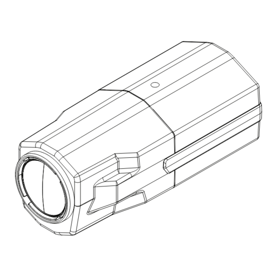
Page 9: Overview
Overview Front View Camera Mount (Top and Bottom) Camera Mount Serial (Top and Bottom) Number Tag Serial Number Tag Feature Description Camera Mounts Mounting points for the camera. Mounts accept 1/4” - 20 UNC bolts commonly found on mounting brackets. Serial Number Tag Product serial number and part number label. -
Page 10: Rear View
Rear View Link LED Connection Status LED Power Connector Block Ethernet Port Audio/Video Connector I/O Terminals Feature Description Ethernet Port Accepts an Ethernet connection to a network. Server communication and image data transmission occurs over this connection. Also receives power when it is connected to a network that provides Power over Ethernet. -
Page 11: Installation
• Mounting bracket, enclosure or tripod. Camera Package Contents Ensure the package contains the following: • ClearPix High Definition IP Camera • Terminal block Installation Steps Complete the following procedures to install the camera. Mounting the Camera on page 3... -
Page 12: Connecting Cables
Caution — This camera is designed for indoor use only. Warning — Use only UL-listed mounting bracket suitable for the mounting surface and minimum 0.7 kg (1.5 lb) weight. Connecting Cables Refer to the diagrams in the Overview section for the location of the different connectors. -
Page 13: Assigning An Ip Address
Zeroconf, the IP address is in the 169.254.0.0/16 subnet. The IP address settings can be changed using one of the following methods: • (Recommended) ClearPix Camera Installation Tool software application. • Camera's web browser interface: http://<camera IP address>/ •... -
Page 14: Aiming And Focusing The Camera
Aiming and Focusing the Camera Use the ClearPix Camera Installation Tool to aim and focus the camera. Consult the software user guide for more information. In the Image and Display settings dialog box, use the Zoom controls to achieve the desired zoom position for the camera. -
Page 15: Cable Connections
Cable Connections Connecting External Power NOTE: Do not perform this procedure if Power over Ethernet (POE) is used. If PoE is not available, the camera needs to be powered through the removable power connector block. Refer to the diagrams in this guide for the location of the power connector block. -
Page 16: Connecting To External Devices
Connecting to External Devices External devices are connected to the camera through the I/O terminal. The pinout for the I/O terminal is shown in the following table and diagram. Table:External I/O Terminals Function Description Ground Ground Input To activate, connect the Input to the Ground pin. -
Page 17: Connecting To Microphones, Speakers And Video Monitors
When the camera flicker control is set to 60 Hz, the video output signal is NTSC. When the flicker control is set to 50 Hz, the video output signal is PAL. Use the ClearPix Camera Installation Tool to configure the camera’s flicker control in the Image and Display setup. -
Page 18: Led Indicators
LED Indicators Once the camera is connected to the network, the Connection Status LED will display the camera’s progress in connecting to the Network Video Management software. The following table describes what the LEDs indicate: Table:LED Indicators Connection Connection Description State Status LED Obtaining IP... -
Page 19: Reset To Factory Default Settings
Reset to Factory Default Settings If the camera no longer functions as expected, you can choose to restore the camera to its factory default settings. Use the firmware revert button to reset the camera. Firmware Revert Button Figure: The firmware revert microswitch on the rear of the camera. Disconnect power from the camera. -
Page 20: Setting The Ip Address Through The Arp/Ping
Setting the IP Address Through the ARP/Ping Method Complete the following steps to configure the camera to use a specific IP address: Locate and copy down the MAC Address (MAC) listed on the Serial Number Tag for reference. Open a Command Prompt window and enter the following commands: arp -s <New Camera IP Address>... -
Page 21: Specifications
Specifications FBxxDN-H2 CFBxxDN-H2 MFBxxDN-H2 Camera Audio Input Line input, A/V mini-jack (3.5 mm) Video Output NTSC/PAL, A/V mini-jack (3.5 mm) Lens 4.7-84.6mm, F1.6, auto iris 3-9mm, F1.2, P-Iris 9-22mm, F1.6, P-Iris Network Network 100Base-TX Cabling Type CAT5 Connector RJ-45 ONVIF compliant (www.onvif.org) Security Password protection, HTTPS encryption, digest authentication, WS authentication, user access log... -
Page 22: Limited Warranty & Technical Support
ClearPix’s entire liability and your exclusive remedy against ClearPix for any failure of this product to operate properly. In no event shall ClearPix be liable for any indirect, incidental, special, consequential, exemplary, or punitive damages whatsoever (including but not limited to, damages for loss of profits or confidential or other...
Need help?
Do you have a question about the CFB12DN-H2 and is the answer not in the manual?
Questions and answers