Graco G-Max 7900 Instructions Manual
Airless 3300 psi (227 bar, 22.7 mpa) maximum working pressure
Hide thumbs
Also See for G-Max 7900:
- Instruction manual (73 pages) ,
- Manual (28 pages) ,
- Instructions and parts list (28 pages)
Table of Contents
Advertisement
Instructions
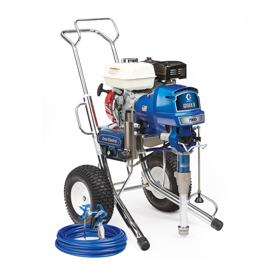
G-Max
Paint Sprayer
For Portable Airless Spraying of Architectural Coatings and Paints.
3300 psi (227 bar, 22.7 MPa) Maximum Working Pressure
Models
NOTE: All models are not available in all countries.
Model
Series
232630
B
Hi-Boy with RAC 5 tip, gun
B
232631
232632
B
Lo-Boy with RAC 5 tip, gun
B
232633
233008
A
Important Safety Instructions
Read all warnings and instructions in this
manual. Save these instructions.
Related Manuals
Manual
Operation
Displacement Pump
Spray Gun
Spray Tip
PC Board
Drain Valve Kit
®
7900 Airless
Description
Hi-Boy
and hose
Lo-Boy
and hose
Hi-Boy with Gauge Kit
Manual Number
308867
307898
309091
309055
308919
308961
308870G
EN
Advertisement
Table of Contents

Related Manuals for Graco G-Max 7900


Summary of Contents for Graco G-Max 7900
- Page 1 Instructions ® G-Max 7900 Airless Paint Sprayer 308870G For Portable Airless Spraying of Architectural Coatings and Paints. 3300 psi (227 bar, 22.7 MPa) Maximum Working Pressure Models NOTE: All models are not available in all countries. Model Series Description 232630 Hi-Boy Hi-Boy with RAC 5 tip, gun 232631...
-
Page 2: Table Of Contents
Model 232632, 232633 ....35 Graco Warranty ......36... -
Page 3: Warnings
Check hoses and parts for signs of damage. Replace any damaged hoses or parts. • This system is capable of producing 3000 psi (210 bar/21 MPa). Use Graco replacement parts or accessories that are rated a minimum of 3000 psi (210 bar/21 MPa). - Page 4 Warnings WARNING EQUIPMENT MISUSE HAZARD Misuse can cause death or serious injury. • Do not operate the unit when fatigued or under the influence of drugs or alcohol. • Do not exceed the maximum working pressure or temperature rating of the lowest rated system component.
-
Page 5: Component Identification
Component Identification Component Identification 202 Main hose 203 Whip end hose 204 Contractor gun with RAC 5 DripLess tip guard and 517 size SwitchTip Model 232631 9034B Pressure Control Switch ON/OFF, enables/disables clutch function and pressure control Pressure Adjusting Knob Controls fluid outlet pressure Air Cleaner* Filters air entering the carburetor... -
Page 6: Maintenance
Maintenance Maintenance Maintenance Checklist NOTE: For detailed engine maintenance and specifica- tions, refer to separate Honda Engines Owner's Manual, • DAILY: Check engine oil level and fill as necessary. supplied. • DAILY: Check hose for wear and damage. Pressure Relief Procedure •... -
Page 7: Troubleshooting
Troubleshooting Troubleshooting Problem Cause Solution Engine won't start Engine switch is OFF Turn engine switch ON Engine is out of gas Refill gas tank. Honda Engines Owner's Manual. Engine oil level is low Try to start engine. Replenish oil, if necessary. - Page 8 1.7 +0.2W; if not, replace clutch coil 241121. Have pressure control checked by authorized Graco dealer. Clutch is worn or damaged Replace clutch. Page 13. Pinion assembly is worn or dam- Repair or replace pinion assembly.
- Page 9 Troubleshooting Problem Cause Solution Excessive paint leakage into throat Throat packing nut is loose Remove throat packing nut spacer. packing nut Tighten throat packing nut just enough to stop leakage. Throat packings are worn or dam- Replace packings. Manual 308798. aged Displacement rod is worn or dam- Replace rod.
-
Page 10: Drive Housing
Rollers Rollers Drive Housing Removal Removal 1. Relieve pressure, page 6. 1. Relieve pressure, page 6. 2. Remove six cap screws (10) lock washers (9) and 2. Remove six cap screws (10) lock washers (9) and cover assembly (24) (F . - Page 11 Rollers Cam Follower Bearings Installation 1. Liberally apply bearing grease (supplied with replacement gear cluster) to gear cluster (18), Removal washers (82) and (83) (F . 2, page 10) and to areas called out by note 1. Use full 0.68 pint (0.32 liter) of grease for GMax 7900.
- Page 12 Rollers 9047A Installation NOTE: All Steps refer to F . 4. 1. Install two cam follower bearings (20c). 2. Install cam follower plate (20b). 3. Install two retainer rings (20d). 4. Drive in pump pin (101) until it engages with pump pin retaining clip (20a).
-
Page 13: Pinion Assembly / Rotor / Field / Shaft / Clutch
Pinion Assembly / Rotor / Field / Shaft / Clutch Pinion Assembly / Rotor / Field / Shaft / Clutch Removal If pinion assembly (19) is not removed from clutch hous- ing (5), do 1. through 4. Otherwise, start at 5. 1. - Page 14 Pinion Assembly / Rotor / Field / Shaft / Clutch Installation ®1 9. Apply Locktite to screws. Install four screws (16) and lock washers (17) (F . 13). Alternately torque 1. Lay two stacks of two dimes on smooth bench sur- screws to 125 in-lb (14 N.m) until rotor is secure.
-
Page 15: Clamp
Clamp Clamp Clutch Housing Removal Removal NOTE: All Steps refer to F . 15. NOTE: All Steps refer to F . 16. Face of clutch housing 1.812 +.010 in. (46.02 +.25 mm) Torque to 125 +.10 in-lb (14 +1.1 Nm) Chamfer this side . -
Page 16: Engine
Engine Engine Removal Installation 1. Remove Pinion Assembly/Rotor/Field/Pinion/Clutch, Clamp and Clutch Housing. See instructions begin- ning on pages 13. 2. Disconnect all necessary wiring (F . 17). Green To the field To the engine . 17 . 18 3. Remove two lock nuts (71) and screws (70) from base of engine (F . -
Page 17: On / Off Switch
On / Off Switch On / Off Switch NOTE: All Steps refer to F . 19. 318a 318z 318aa Locate switch terminals as shown . 19 Removal Installation 1. Install new ON/OFF switch (309) so tabs of switch snap into place on inside of pressure control hous- ing. -
Page 18: Pressure Control
Pressure Control Pressure Control Control Board NOTE: All Steps refer to F . 20. Green Black (Ref) (Ref) Potentiometer Pressure Red (+) transducer 318z 318aa (Ref) (Ref) Violet (Ref) (Ref) . 20 Removal Installation When installing replacement control board, follow instructions with control board to set model type. -
Page 19: Pressure Control Transducer
Pressure Control Pressure Control Transducer NOTE: All Steps refer to F . 21. 318a 318z 318aa Locate switch terminals as shown . 21 Removal Installation 1. Install packing o-ring (318aa) and pressure control transducer (318z) in filter housing (318a). Torque to 30-35 ft-lb. -
Page 20: Pressure Adjust Potentiometer
Pressure Control Pressure Adjust Potentiometer NOTE: All Steps refer to F . 22. 318a 318z 318aa Locate switch terminals as shown . 22 Removal Installation 1. Install seal (311) on potentiometer (310). 2. Install pressure adjust potentiometer (310), shaft nut, lock washer (310) and potentiometer knob 1. -
Page 21: Control Board Diagnostics
Pressure Control Control Board Diagnostics 1. Remove five screws (307) and cover (322) (F . 22). 3. Turn ON/OFF switch ON. 2. Start sprayer. 4. Observe LED operation and reference following table: LED Blinks Sprayer Operation Indicates What to do 1. -
Page 22: Displacement Pump
Displacement Pump Displacement Pump Removal 6. Loosen locknut by hitting firmly with a 20 oz (maxi- mum) hammer (F . 25). Unscrew pump. 1. Flush pump. 2. Cycle pump with piston rod (222) in lowest position . 23). . 25 NOTE: See manual 308798 for pump repair instruc- tions. -
Page 23: Pump Pin Clip
75 +5 ft-lb (102 Nm) (F . 27). 2. Remove two bolts (86), washers (25), pump bracket (85), pail hook (94) and shield (95). 5. Fill packing nut with Graco TSL until fluid flows onto the top of seal. 3. Remove clip (20a). . 27... -
Page 24: Parts List & Drawing - Pinion Assembly
Parts List & Drawing - Pinion Assembly Parts List & Drawing - Pinion Assembly Ref No. 19 and 20 Ref No. 19: Pinion Housing Assembly 241116 Part No. Description Part No. Description 193656 CAM FOLLOWER PLATE 241121 PINION HOUSING, coil 114691 CAM FOLLOWER BEARING 105489... -
Page 25: Parts Drawing - Hi-Boy Sprayer
Parts Drawing - Hi-Boy Sprayer Parts Drawing - Hi-Boy Sprayer Model 232630 and 233008 DETAIL A Label Ref 11 See page 17 for the parts. See manual 308798 for the parts. See page 22 for the parts. See page 22 for the parts. Ref 35 9027A DETAIL A... -
Page 26: Parts List - Hi-Boy Sprayers
Parts List - Hi-Boy Sprayers Parts List - Hi-Boy Sprayers Models 232630, 232631 and 233008* Part No. Description Part No. Description 189920 STRAINER 114530 ENGINE 240795 HOSE, coupled 113084 RIVET, blind 193394 NUT, retaining 192014 PLATE, indicator 241324 CART FRAME 241113 CLUTCH, assembly, includes 4a, 4b, 15, 17, 72, 80... - Page 27 Parts List - Hi-Boy Sprayers Part No. Description 100214 WASHER, lock spring 114687 CLIP, retainer HUB, armature 114699 WASHER, thrust 114672 WASHER, thrust 194118 BRACKET, pump 110343 SCREW, cap, sch 240997 CONUDCTOR, ground 110249 ADAPTER, male elbow, 90° 108851 WASHER 241540 PAIL HOOK Repair Kit, includes 95...
-
Page 28: Parts Drawing - Lo-Boy Sprayer
Parts Drawing - Lo-Boy Sprayer Parts Drawing - Lo-Boy Sprayer DETAIL A Label Ref 11 See page 17 for the parts. See manual 308798 for the parts. See page 22 for the parts. Bottom View Ref 35 30ae 30ad DETAIL A 30ac 30ab 30aa... -
Page 29: Parts List - Lo-Boy Sprayers
Parts List - Lo-Boy Sprayers Parts List - Lo-Boy Sprayers Models 232632, 232633 Part No. Description 241288 ASSEMBLY, tube suction Part No. Description 241269 . TUBE, suction, 30 gallon 114530 ENGINE (120 L) included 30aa - 3ae 113084 RIVET, blind 30aa 198119 .. - Page 30 Parts List - Lo-Boy Sprayers Part No. Description 162485 NIPPLE, 3/8-18 npsm(m) x 3/8 npt(m) 194178 HOSE, drain 241718 DEFLECTOR 110837 SCREW, flng, hex hd, 5/16-18 x 1-1/2 in. 110838 LOCKNUT, heavy, hex hd, 5/16-18 101682 SCREW, cap sch 108842 SCREW, cap sch 100214 WASHER, lock spring...
-
Page 31: Model 232630 Through 232633
Parts List - Lo-Boy Sprayers Model 232630 through 232633 Models 232630 through 232633 318f 318e 318d 318b 318c 318z 318aa 318a 318g 318h 318m 318n 318l 318j 318k 8716A 308870G... -
Page 32: Parts List - Hi-Boy Sprayers
Parts List - Hi-Boy Sprayers Parts List - Hi-Boy Sprayers Models 232630 through 232633 Part No. Description 318z 240314 TRANSDUCER, pressure Part No. Description control includes 318aa 193653 PLATE, control 318aa 111457 O-RING 241093 BOARD, PC 110997 SCREW, flange, hex 111839 SCREW, mch pan, 6-32 x 114532... -
Page 33: Parts List - Complete Sprayers
238358 HOSE, grounded, nylon; 3/16. Order the labels from your Graco distributor. ID; cpld 1/4 npsm(m) x 1/4 npsm(f) swivel; 3 foot (0.9 m); spring guards both ends Language Part No. -
Page 34: Wiring Diagram
Wiring Diagram Wiring Diagram Green Black (Ref) (Ref) Potentiometer Pressure Red (+) transducer 318z 318aa (Ref) (Ref) Violet (Ref) (Ref) 308870G... -
Page 35: Technical Data
Technical Data Technical Data Honda GX160 Engine Power Rating @ 3700 RPM ANSI 5.5 horsepower DIN 6270B/DIN 6271 2.9 Kw - 4.0 Ps 3.6 Kw - 4.9 Ps Maximum working pressure 3300 psi (227 bar, 22.7 MPa) Noise Level Sound power 105 dBa per ISO 3744 Sound pressure 96 dBa measured at 3.1 feet (1 m) -
Page 36: Graco Warranty
Graco distributor to the original purchaser for use. With the exception of any special, extended, or limited warranty published by Graco, Graco will, for a period of twelve months from the date of sale, repair or replace any part of the equipment determined by Graco to be defective.
Need help?
Do you have a question about the G-Max 7900 and is the answer not in the manual?
Questions and answers
I'm trying to find out how to unclog a a standard Graco 7900 Max my machine is used for spring asphalt a motion waterproofing I think I clogged it I love the piston
To unclog a Graco G-Max 7900, follow these steps:
1. Clean the Strainer – If the strainer (31) is clogged, remove and clean it.
2. Service the Piston Ball – Ensure the piston ball (25) is seating properly; service if necessary.
3. Replace Worn Packings – If the piston packings are worn or damaged, replace them.
4. Replace O-ring – If the O-ring (227) in the displacement pump is worn or damaged, replace it.
5. Clean the Intake Valve Ball – Ensure the intake valve ball is seating properly and clean it if needed.
6. Increase Engine Speed – If the engine speed is too low, increase the throttle setting.
7. Check Pressure Setting – Increase the pressure if it is too low.
8. Clean Filters or Tip – If the fluid filter (318), tip filter, or spray tip is clogged or dirty, clean them.
9. Use a Larger Hose – If there is a large pressure drop in the hose when spraying heavy materials, use a larger diameter hose or reduce its length.
For detailed instructions, refer to the appropriate manual sections.
This answer is automatically generated