Table of Contents

Related Manuals for Microtech Xpress

Summary of Contents for Microtech Xpress
- Page 1 Xpress Disc Production System Hardware Manual Revision 4 Microtech Systems, Inc. 2 Davis Drive Belmont, CA 94002 USA 650/596-1900 Phone 650/596-1915 microtech.com info@microtech.com email Document # 003-0075-04 Revised April 2004...
- Page 3 Regulatory Compliance Statements Notice for USA Federal Communications Commissions (FCC) Statement This equipment has been tested and found to comply with the radiated energy limits for a Class A digital device, in accordance with FCC CFR 47 Part 15 Rules and Regulations. (1) This device may not cause harmful interference, and (2) this device must accept any interference received, including interference that...
-
Page 5: Table Of Contents
Xpress Contents.................................8 Xpress Assembly Procedures ..........................9 Xpress Basics ............................ 13 Powering Up Xpress ...............................14 The Xpress Desktop..............................15 Checking the Xpress Software Configuration ....................16 Initial System Calibration .............................17 Testing Xpress .................................19 Placing Discs on Spindles .............................20 Shutting Down Xpress ............................21 Calibrating Xpress........................... 23 Calibrating Xpress ..............................24... -
Page 7: Introduction
Introduction... -
Page 8: Introducing Xpress
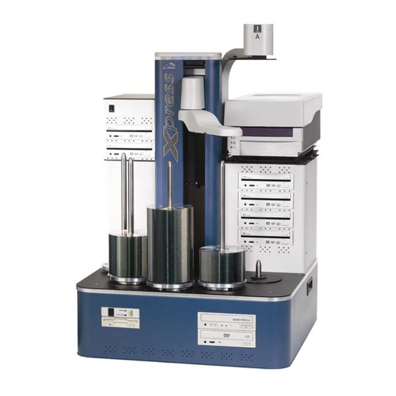
Xpress’s Parts The following section shows and identifies all the important parts of your Xpress. These components will be referred to later in the manual; take a few moments to become familiar with them. The main parts of the Xpress production system are indicated below (front view). - Page 9 The disc spindles hold discs in various stages of processing. There are four full height spindles for holding blank and completed discs, and one shorter reject spindle. All spindles can be lifed off and on for easy disc handling. Xpress Back View Camera Light Shield/Camera Mount Disc Camera Support Boom...
-
Page 10: Xpress Specifications
Xpress’s Control Panel The control panel on the front of Xpress’s base unit contains the power switch and several indicator lights. Disc Drive Activity Lights Power Switch Floppy Drive Besides the labeled indicator lights for power and the hard drive, there are four lights in a column, these lights are used to indicate the activity on drives or buses. -
Page 11: Setting Up Xpress
Setting Up Xpress... -
Page 12: Disc Production Workspace
Disc Production Workspace The workspace for the Xpress disc production system should be in an Important Unpacking environment free of dust and debris. Contamination can adversely affect Information production yield, degrade the quality of the discs produced, and reduce Be sure to save all packing the life of the equipment. -
Page 13: Checking In Your Shipment
Monday through Friday from 7:30 AM to 6:00 PM Pacific Time. Please contact us with any questions or problems during the unpacking, installation, and set up of the Xpress disc production system. If the shipping cartons are present and not damaged, start setting up a workspace for your production system. -
Page 14: Xpress Contents
Camera Cable Calibration Disc During unpacking, visually inspect parts for dents, scratches or other damage. If any parts are damaged, call Microtech’s Customer Support Department at 650-596-1900 7:30 – 5:30 PST Microtech Systems will only accept merchandise returned in the original shipping container. -
Page 15: Xpress Assembly Procedures
Xpress Assembly Procedures Base Unit 1. Place Base Unit on Work surface. 2. Set keyboard, mouse, Software Key, and cables aside for later connection. Drive Enclosure 1. Remove thumbscrews (2) from the back of the Drive Enclosure – set aside. - Page 16 2. Connect Printer Power Cord to port on back of Printer, plug opposite end into standard electrical outlet. 3. Install Software Key into any USB port on back of Xpress Base Unit. Note: If using ImageAligner Option, insure that Software Key is installed in Parallel Port on back of Xpress Base Unit.
- Page 17 PRINTER IS READY FOR INITIAL TESTING Additional Cables 1. Connect Xpress Main Power Cord to port on back of Base Unit, plug into standard 110v electrical outlet. 2. Install Software Key into any USB port on back of Base Unit.
-
Page 19: Xpress Basics
Xpress Basics... -
Page 20: Powering Up Xpress
Once Xpress is set up, test it to make sure everything is operating properly. This chapter covers two quick test procedures. The first is an automated test, that confirms that the system mechanics are working, and that discs can be picked up, dropped and moved around correctly. -
Page 21: The Xpress Desktop
The ImageMaker MJ (“Classic”) icon Starts the optional ImageMaker MJ software for disc duplication. Please refer to the software manual. The Xpress Calibration icon Starts the Xpress calibration utility used for calibrating the system. The CD-R icon EMOTE Starts the CD-R... -
Page 22: Checking The Xpress Software Configuration
CD Color Printer Pro LPT1 Identify the type of ImageAutomator system In the field labeled The ImageAutomator is a model …, select Xpress. Save any changes made. If any changes to the configuration have • been made click the Update button before closing the utility. If no changes have been made, click Close. -
Page 23: Initial System Calibration
The printer tray will then open, and the disc will be picked up from the printer tray, and the printer tray will close. 5. If no printer is installed, the disc will be picked up from the disc writer drive tray and dropped on spindle 4. Xpress Basics... - Page 24 After starting the test, this button name will automatically change to Stop Continuous. To stop the test, click this button. If the problem recurs, calibration (adjustment) of the system is necessary. (See the following chapter, Calibrating Xpress for complete instructions.) Xpress Basics...
-
Page 25: Testing Xpress
Find the field labeled Disc Name near the top. Click the arrow at the right of this field to open a list box of available images. There are two images included with every Xpress system, one for systems with a printer installed and one for systems without a printer. (The one for printer-equipped systems will also print the disc copies.) Click on your... -
Page 26: Placing Discs On Spindles
Placing Discs on Spindles As an automated disc production system, Xpress transports discs to various processing stations internally. The operator’s only physical task is to load blank discs for processing on the input spindle(s) and remove finished discs from the output spindle(s). -
Page 27: Shutting Down Xpress
Shutting Down Xpress When the job completes, please follow the standard Windows shut down CAUTION: Do not shut procedures. down the system if there are any production jobs running on it. It may not be obvious if a job is... -
Page 29: Calibrating Xpress
Calibrating Xpress... -
Page 30: Calibrating Xpress
Calibrating Xpress To work properly, Xpress needs to be correctly calibrated. Xpress is calibrated at the factory and should not need recalibration. Improper handling during shipping may make this step necessary. If discs are not picked up from the input spindles, are being dropped off the trays or output spindles or are going into drive or printer trays cockeyed, the system must be recalibrated. -
Page 31: Microtech Support
Microtech Support If you are having problems with your Xpress, before calling Microtech Systems support line please check the following: 1. Check all external connections 2. Check for good power 3. Make sure your system is on a sturdy and level surface 4. -
Page 33: Index
Starting the System ..........14 Initial System Calibration ........17 System Calibration ...........24 Initial System Checkout .......... 19 Systems Parts ..............2 Microtech Support ........... 25 Windows NT Placing Discs on Spindles ........20 starting Windows ..........14 Shutting Down the System ........21 Xpress Parts..............8...
Need help?
Do you have a question about the Xpress and is the answer not in the manual?
Questions and answers