Table of Contents
Advertisement
Quick Links
Advertisement
Table of Contents

Summary of Contents for Sonex Aircraft Aerovee 2.1
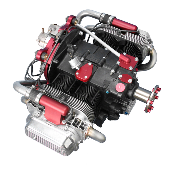
- Page 1 $35.00 ASSEMBLY and INSTALLATION ACV-R02 Rev Z. 01/14/2015 Applies to AeroVee s/n 0440 and up. Includes top-mounted oil cooler. Photo for illustration only and does not represent the specific contents of your kit. A Product Line of Sonex Aircraft LLC...
-
Page 2: Table Of Contents
AeroVee 2.1 TABLE of CONTENTS Rev Z. 01/14/2015 Contents Trigger Shaft Installation ........... 34 Your feedback is welcome and encouraged as we continue to Spark Plug Installation ..........35 improve this manual. Please send comments to tech@aerocon- Intake Manifold Installation ........36 versions.com. -
Page 3: Important
Sonex Aircraft LLC and its agents will in no event be liable the back of the physical manual supplied with that engine. -
Page 4: Aerovee Engine Kit Documentation
Information on joining this list is located on the the back of the physical manual supplied with that engine. AeroConversions website at aeroconversions.com. Copies of (most) packing lists are archived by Sonex Aircraft AeroConversions Tech Support and you may request an electronic (PDF) copy. To get a copy,... -
Page 5: Specifications
AeroVee 2.1 SPECIFICATIONS Rev Z. 01/14/2015 Weights and Dimensions: Weight (Less Oil and Exhaust): with Standard Pistons and Barrels ......160 lbs. Length ................24.25” Width ................30” Height ..............20.0625” 4.875" 24.25" 30.00" 18.875" 20.0625" 21.875" w/ optional air cleaner Mount Dimensions (Viewed from behind) -
Page 6: General Specifications
AeroVee 2.1 SPECIFICATIONS Rev Z. 01/14/2015 General Specifications Cylinder Identification, Engine Orientation, (Subject to change without notice) Power and Displacement: and Firing Order HP @ 3400 RPM ............80 HP Cylinder Identification Static RPM @ WOT (with correct propeller) ..3000 RPM For assembly and maintenance, the AeroVee uses the cylinder Bore ................ -
Page 7: Before You Begin
Photos in this manual are included to illustrate specific steps Copies of (most) packing lists are archived by Sonex Aircraft and may not accurately illustrate what an engine looks like and you may request an electronic (PDF) copy. -
Page 8: Crankshaft Assembly
FoRCe pARTS onTo The CRAnKShAFT. if a part does not go into place on the crankshaft, STop. do not force it on and do not try to remove it. Contact Sonex Aircraft LLC before continuing. Sonex Aircraft © 2014 All Rights Reserved... - Page 9 AeroVee 2.1 CRANKSHAFT ASSEMBLY Rev Z. 01/14/2015 __9. Align the keyway of the Prop Hub with the forward __ 3. Install the Timing Gear woodruff key installed in the crankshaft and tap the with the two machined prop hub into place using a mallet and block of wood.
-
Page 10: Cam Assembly
AeroVee 2.1 CAM ASSEMBLY Rev Z. 01/14/2015 Tools Required: __1. Align the machined dot __ Socket Wrench on the face of the Cam Gear (arrow in photo) __ 13mm Socket with the slot in the __ Torque Wrench (20 ft.-lbs. capacity) Cam Shaft. -
Page 11: Connecting Rod Assembly
.002" and .0025". When assembling new Torque) to the threads of each rod bolt and install. parts, as provided in the AeroVee 2.1 kit, the proper clearance Torque each bolt in four steps: is often assumed. When rebuilding an engine using remanufac- ___first to 8 ft.-lbs. -
Page 12: Crank Case Preparation
AeroVee 2.1 CRANK CASE PREPARATION Rev Z. 01/14/2015 Tools Required: Assembly Instructions: __ Flat Blade Screwdriver __1. Install the head studs as shown in the photos below. __ Rubber Mallet __ Fine File Cylinder Head Stud Placement __ White Lithium Grease = Short Cylinder Head Stud (7-3/8"... - Page 13 AeroVee 2.1 CRANK CASE PREPARATION Rev Z. 01/14/2015 __2. Lay the case on it's side so the oil pressure relief ports __8. Insert the short spring in the bottom of the case are accessible. behind the non-grooved plunger. Oil Pressure Relief Ports __9.
- Page 14 AeroVee 2.1 CRANK CASE PREPARATION Rev Z. 01/14/2015 __12. The flanged cam bearing for the right case half must __14. Test fit each Valve Lifter in a guide. The lifters must have its alignment tab filed off. File the tab off with a slide freely in the guides.
- Page 15 AeroVee 2.1 CRANK CASE PREPARATION Rev Z. 01/14/2015 __17. Install one (1) Dowel Pin in the left case half. Make sure it is fully inserted. __18. Install one half of the Split Main Bearing (from Main Bearing Set, ACV-P01-57) into the middle journal of each case half, carefully aligning the recess in the bear- ing with the dowel pin in the journal.
-
Page 16: Crank Case Assembly
AeroVee 2.1 CRANK CASE ASSEMBLY Rev Z. 01/14/2015 __3. impoRTAnT! Temporarily mate the case halves and Tools Required: rotate the crankshaft. Listen and "feel" for a knock __ White Lithium Grease which may indicate the case is interfering with the con- __ "Red"... - Page 17 AeroVee 2.1 CRANK CASE ASSEMBLY Rev Z. 01/14/2015 __7. Align the 8 holes in the center of the flywheel with __13. Check your shim selection by sliding the shims, to- the dowel pins on the end of the crankshaft. The hole...
- Page 18 AeroVee 2.1 CRANK CASE ASSEMBLY Rev Z. 01/14/2015 __16. Apply Permatex Avia- __21. In the order shown in the photo, re-torque the 6 large tion Form-A-Gasket #3 nuts to 25 foot-pounds. do not exceed 25 foot-pounds. or Flange Sealant to the __22.
- Page 19 AeroVee 2.1 CRANK CASE ASSEMBLY Rev Z. 01/14/2015 __26. Install and lightly tighten an ACV-Z01-16 hex head cap screw, two (2) ACV-Z01-26 washers, and an ACV- Z01-23 stop nut in each of the three through- holes which serve to join to two case halves.
-
Page 20: Piston And Cylinder Assembly
AeroVee 2.1 PISTON & CYLINDER ASSEMBLY Rev Z. 01/14/2015 Tools Required: tween the top of the piston and the top of the cylinder). If the piston is below the top of the cylinder you have a __ Needle-Nose Pliers positive (+) deck height. If the piston is higher than the __ SAE 30 Motor Oil top of the cylinder, you have a negative (-) deck height. -
Page 21: Compression Ratio Chart
AeroVee 2.1 PISTON & CYLINDER ASSEMBLY Rev Z. 01/14/2015 __12. Remove excessive sealant and tap the cylinder with a rubber mallet to seat it in position. __13. Repeat steps 10 through 12 for the other cylinders. __14. Install the super tin (below) under the cylinders and cylinder head. -
Page 22: Cylinder Head Installation
AeroVee 2.1 CYLINDER HEAD INSTALLATION Rev Z. 01/14/2015 Parts Required: __3. Align the cylinder head __ Cylinder Head Nuts and Washers, from ACV-P01-86 with the engine studs and cylinders and then __ Copper Cylinder Head Gaskets, 0.060 Thick, ACV-P01-92 install the push rod... -
Page 23: Rocker Shaft Installation
ROCKER SHAFT INSTALLATION AeroVee 2.1 Rev Z. 01/14/2015 Note: Steps 3 through 19 apply to one side of the engine at a Parts Required: time and will be repeated for each side. __ Push Rods, ACV-P06-51 __ Pushrod Measuring Tool __ 3. - Page 24 AeroVee 2.1 ROCKER SHAFT INSTALLATION Rev Z. 01/14/2015 __ 5. Observe the lateral alignment of each swivel pad to __ 6. Torque the hex head cap screws on the end of the rocker its corresponding valve stem. Arrange the spacers on shaft assembly to 25 foot-pounds.
-
Page 25: Oil Screen Installation
AeroVee 2.1 OIL SCREEN INSTALLATION Rev Z. 01/14/2015 __ 5. Install the oil drain plug and included metal/copper Tools Required: gaskets, or the optional oil temp sender w/gasket. __ Socket Wrench __ 10 mm Socket Note: On engine cases requiring an ACV-P01-12 Oil... -
Page 26: Oil Pump Installation
AeroVee 2.1 OIL PUMP INSTALLATION Rev Z. 01/14/2015 important! Failure to properly align the passages in Tools Required: the ported cover plate will result in low oil pressure __ Socket Wrench and engine damage. __ 13 mm Socket __ Plastic Mallet... -
Page 27: Oil Seal Installation
AeroVee 2.1 OIL SEAL INSTALLATION Rev Z. 01/14/2015 Tools Required: __ High Temperature RTV Silicone Gasket Maker __ VW Oil Seal Installation Tool (optional, recommended) __ Rubber Mallet Parts Required: __ End Shims, ACV-P02-19 __ Oil Seal, ACV-P01-68 Assembly Instructions... -
Page 28: Prop Drive Lug Installation
AeroVee 2.1 PROP DRIVE LUG INSTALLATION Rev Z. 01/14/2015 Tools Required: __ 5/16-18" x 2” Hex Head Cap Screw (not supplied in kit) __ 5/16-18 Nut (not supplied in kit) __ 5/16 Washer (not supplied in kit) __ 5/8" Socket... -
Page 29: Valve Adjustment
AeroVee 2.1 VALVE ADJUSTMENT Rev Z. 01/14/2015 Tools Required: __ 0.006" Feeler Gauge __ Flat blade screw driver __ Socket Wrench __ 13 mm Socket Parts Required: __ Valve Covers, ACV-P01-15 Assembly Instructions: __ 1. Rotate the prop hub until the # 1 cylinder is at top dead center and both the intake and the exhaust valves are closed (valve springs fully extended). -
Page 30: Block-Off Plates And Plugs
AeroVee 2.1 BLOCK-OFF PLATES and PLUGS Rev Z. 01/14/2015 __ 4. Some engines require Parts Required the installation of an __ Gasket Set (partial), ACV-P02-15 oil temperature plate __ ACV-Z01-18 Bolts, Qty 6 below cylinder #2. It is __ Machined Breather Plate, ACV-P01-85... -
Page 31: Flywheel Installation
AeroVee 2.1 FLYWHEEL INSTALLATION Rev Z. 01/14/2015 Tools Required: __3. Install wavy washer and gland nut with Locktite __Socket Wrench 272. Torque to 227 ft-lbs. __36mm Socket Note: A piece of wood __Torque Wrench temporarily bolted to __Permatex High Temp Red RTV Silicone Gasket... -
Page 32: Flywheel Magnet Orientation Check
AeroVee 2.1 FLYWHEEL MAGNET ORIENTATION Rev Z. 01/14/2015 Sonex Aircraft © 2014 All Rights Reserved... -
Page 33: Accessory Plate Installation
AeroVee 2.1 ACCESSORY PLATE INSTALLATION Rev Z. 01/14/2015 Tools Required: __ 3. Match the acces- __ Socket Wrench sory plate to the raised __ 13mm Socket groove on the back of __ 13mm Ignition Wrench the engine case. __ 9/64" Allen Wrench __ 4. -
Page 34: Trigger Shaft Installation
AeroVee 2.1 TRIGGER SHAFT INSTALLATION Rev Z. 01/14/2015 __ 2. Line up the witness hole in the trigger shaft (C) with the Tools Required witness hole in the flywheel. Apply Locktite 242 to each __ 9/64" Hex Drive of the four (4) ACV-Z01-81 flat head cap screws and __ Locktite 242 install them loosely. -
Page 35: Spark Plug Installation
AeroVee 2.1 SPARK PLUG INSTALLATION Rev Z. 01/14/2015 Tools Required: __ 11/16” Spark Plug Socket Wrench __ 0.018" & 0.032 Feeler Gauges __ Anti-Seize Compound Parts Required: __ Autolite 4163 Spark Plugs (Qty 8), ACV-P01-21 Plug Installation: __ 1. Gap four (4) TOP spark plugs to 0.018". -
Page 36: Intake Manifold Installation
AeroVee 2.1 INTAKE MANIFOLD INSTALLATION Rev Z. 01/14/2015 Supplies Required: __4. Thoroughly clean the inside of the manifold __ Permatex Aviation Form-A-Gasket #3 or Flange Sealant before installing it. Parts Required: __5. Secure an intake hose __ AeroInjector, ACV-C07S to each intake elbow... -
Page 37: Alternator Installation
AeroVee 2.1 ALTERNATOR INSTALLATION Rev Z. 01/14/2015 Tools Required Installing the Stator Assembly __ 1. "Paint" the surface of each magnet in the magnet ring __ 9/64" Hex Drive __ Locktite 242 and the outside of the stator with a permanent marker. -
Page 38: Firewall Preparation
AeroVee 2.1 FIREWALL PREPARATION Rev Z. 01/14/2015 Secondary Ignition Coil Installation Parts Required __ Voltage Regulator, ACV-A01-20 Note: The ignition coils must be grounded. In a typical instal- lation the coils will be grounded through the hardware which __ Ignition Coils (Red), Qty. 2, ACV-A01-25 secures them to the firewall. -
Page 39: Mounting The Engine
AeroVee 2.1 MOUNTING the ENGINE Rev Z. 01/14/2015 Parts Required __ Motor Mount Shock Bushings (Qty. 8), ACV-P01-19 __ 3/8" ID x 1.25" OD Fender Washer (Qty. 16), ACV-Z01-40 __ AN4-36A Bolt (Qty. 4, not supplied) __ AN363-428 Nut (Qty. 4, not supplied) -
Page 40: Mount Pin Detail Drawing And Typical Installation
AeroVee 2.1 MOTOR MOUNT PIN DETAIL Rev Z. 01/14/2015 Sonex Aircraft © 2014 All Rights Reserved... -
Page 41: Magnatron Ignition Wiring
Magnatron circuit is closed and the Magnatrons are disabled. how they are internally When the switch is "On" the ground path is open and the wired. Sonex Aircraft LLC Magnatrons become operational. is unable to assist on any This DPST switch would... - Page 42 AeroVee 2.1 MAGNATRON IGNITION WIRING Rev Z. 01/14/2015 __ 1. Attach a 20 gauge (minimum) ground wire to the body of each magnatron. The ground wire may be at- tached to a magnatron mounting bolt, or to one of the "studs" (A) on the metal frame.
-
Page 43: Electronic Ignition Wiring
AeroVee 2.1 ELECTRONIC IGNITION WIRING Rev Z. 01/14/2015 __ 2. Red wire (+12V). Attach to rear terminal screw of right Parts Required hand coil (terminal "B" in photo). __ Electrical Terminals (not supplied) __ Electrical Wire (not supplied) __ 3. Orange wire (Trigger). Attach to the front terminal (ter- minal "A"... -
Page 44: Spark Plug Wires
AeroVee 2.1 SPARK PLUG WIRES Rev Z. 01/14/2015 Parts Required: __2. Slide a boot (included with ACV-A01-24) over the cut end of each spark plug wire. __ Spark Plug Wires, ACV-A01-24 Assembly Instructions: important: The factory crimped ends of each wire will be re-used. -
Page 45: Electronic Ignition Timing
AeroVee 2.1 ELECTRONIC IGNITION TIMING Rev Z. 01/14/2015 Timing the Secondary Ignition Tools Required __ 5/32" hex wrench important: The secondary ignition will spark when the ignition is on and the trigger magnet passes by the sensor. This can cause ignition. Avoid serious injury or death by... - Page 46 AeroVee 2.1 ELECTRONIC IGNITION TIMING Rev Z. 01/14/2015 __ 4. Loosen the socket head cap screw (D) and rotate the Timing Check magnet cap (A) until the mark on the magnet cap (B) is ground Check. Running the engine and performing a mag centered under the sensor (C) of the upper trigger.
-
Page 47: Alternator / Regulator Wiring
AeroVee 2.1 ALTERNATOR / REGULATOR WIRING Rev Z. 01/14/2015 Parts Required __ Electrical Terminals (not supplied) __ Electrical Wire (not supplied) Alternator - Regulator Wiring __ 1. Attach the two wires from the alternator to the two outer terminals of the voltage regulator. It does not matter which wire attaches to which terminal. -
Page 48: Starter Installation / Wiring
AeroVee 2.1 STARTER INSTALLATION / WIRING Rev Z. 01/14/2015 Tools Required: Starter Wiring __ 3/8" Hex Wrench The drawing below illustrates a typical starter wiring sche- matic. This can be modified to suit your needs. Note that a __ Locktite 262... -
Page 49: Oil Breather Tube
AeroVee 2.1 OIL BREATHER TUBE Rev Z. 01/14/2015 Materials Required __ 5/8" O.D. x .035" Aluminum Tube (6061-T6 or 5052-0) __ Permatex High Temp Red RTV Silicone Gasket Breather Installation __ 1. Form an engine breather tube from 5/8 diameter x .035" wall 6061-T6 or 5052-0 aluminum tube. -
Page 50: Oil Cooler Installation Options
AeroVee 2.1 OIL COOLER INSTALLATION OPTIONS Rev Z. 01/14/2015 The AeroVee can be fitted with two different factory-devel- oped oil cooler installations or, in rare circumstances, no oil cooler at all. Your engine kit was shipped with the AeroConversion-specific parts needed for one of the two oil cooler installations detailed on the following pages. -
Page 51: Oil Cooler, Bottom Mount
__ Optional Sonex/AeroVee Baffle Kit (p/n SNX-P30-10) sump to exit through the oil cooler. The following parts are not supplied by Sonex Aircraft. __ Oil Cooler (Jeg's P/N 130-70265) __ AN912-4D Reducer Bushing, Qty. 2 __ AN816-6-6D Straight Flare Fitting, Qty. -
Page 52: Oil Cooler - Top Mount
8. Install the hose assemblies on the oil cooler. Do not use Parts Required (Supplied by Sonex Aircraft) sealing compounds or teflon tape on these fittings. __ Oil Cooler Bypass Plate, ACV-P01-11 9. - Page 53 2. Carefully position the Oil Cooler Mount Plate over the Parts Required seals and bolt the plate to the engine case using the hard- Supplied by/available from Sonex Aircraft: ware identified in the photo below. __ Oil Cooler Mount Plate, ACV-P01-106 __ Rubber gaskets from ACV-P02-15 Gasket Kit __ AN4-13A bolt, Qty.
- Page 54 AeroVee 2.1 OIL COOLER, TOP MOUNT Rev Z. 01/14/2015 4. Remove a 1-5/8" long portion of the front, lower flange of __ 6. Install the optional oil the oil cooler. This is necessary to eliminate interference pressure sender or a 1/8 between the oil cooler's flange and the adapter plate.
-
Page 55: Oil Cooler Removal / Bypass
AeroVee 2.1 OIL COOLER REMOVAL / BYPASS Rev Z. 01/14/2015 Bypassing / Removing a Bottom-Mounted Bypassing / Removing a Top-Mounted Oil Cooler Oil Cooler Parts Required Parts Required __ 6061-T6 Sheet (approx 12"' x 12") __ Oil Cooler Bypass Plate, AeroConversions p/n ACV-P01-56... -
Page 56: Exhaust Installation
__ 4. Attach a spring between each pair of spring clips. It may Parts Required be necessary to shorten the springs for your particular __ Optional Sonex Aircraft Exhaust Kit installation. __ Exhaust Gaskets (included in ACV-P02-15 Gasket Kit). Available separately as p/n ACV-P01-73. -
Page 57: Fuel Supply
AeroInjector should be referenced. the carburetor fuel inlet. If the hose is higher than the fuel inlet Other than the fuel tank (included with your Sonex Aircraft at any point between the gascolator and the AeroInjector, an airframe kit) and the AeroInjector (AeroCarb) included with air pocket can form and hinder fuel flow. - Page 58 AeroVee 2.1 FUEL SUPPLY Rev Z. 01/14/2015 A typical fuel line connection at the AeroInjector Sonex Aircraft © 2014 All Rights Reserved...
-
Page 59: Engine Cooling Baffles
__ ONX-P01-10, For a Onex airframe. their operating limits during normal operation. Sonex Aircraft LLC has developed a fence baffle system specifically for use on Sonex Airframes /AeroVee installations. These system may also be adapted to other airframe installa- tions. -
Page 60: Engine Oil
AeroVee 2.1 ENGINE OIL Rev Z. 01/14/2015 Priming the Engine and Setting Oil Level Parts Required __ 3 quarts approved SAE engine oil. Approved oils are The AeroVee has a 2.75 quart capacity without oil cooler and lines. The following method may be used to achieve the proper listed below. -
Page 61: Start-Up And Break In
AeroVee 2.1 START-UP and BREAK IN Rev Z. 01/14/2015 Bringing your engine to life is exciting and rewarding. These Starting the Engine points and procedures will assure the greatest success. __ 1. Install the correct oil and prime the engine as described in "Engine Oil", previous page. -
Page 62: Maintenance
AeroVee 2.1 MAINTENANCE Rev Z. 01/14/2015 Minimum Maintenance Interval On Annual Inspection ___ Change the oil and wash the oil screen. 1 Hour Accumulated ___ Torque the heads to 18 foot pounds. Do NOT loosen ___ Change the oil and wash the oil screen. -
Page 63: Troubleshooting
AeroVee 2.1 TROUBLESHOOTING Rev Z. 01/14/2015 Engine does not start Possible Cause Remedy 1) Ignition OFF Switch ON 2) Spark plug gaps too large Adjust gaps or replace plugs 3) Closed fuel valve or clogged filter Open valve, replace or clean filter, check... - Page 64 AeroVee 2.1 TROUBLESHOOTING Rev Z. 01/14/2015 Unsatisfactory power output Possible Cause Remedy 1) Ignition failure Check ignition circuits; Check wiring and /or replace ignition units 2) Too much oil in crankcase Check oil level & adjust if necessary 3) Insufficient fuel supply...
-
Page 65: Electrical Schematics
AeroVee 2.1 ELECTRICAL SCHEMATICS Rev Z. 01/14/2015 This page is a quick reference of electrical schematics associ- ated with the AeroVee installation. Detailed instructions for ALTERNATOR WIRING SCHEMATIC each sub-system are provided elsewhere in this manual. STARTER WIRING SCHEMATIC SECONDARY IGNITION SCHEMATIC... -
Page 66: Appendix A: Sonex Cowl Openings
This Appendix details the cowling inlets and outlets of a Important: Even if you do not fit an oil cooler you must Sonex Aircraft cowling fitted to a Sonex, Waiex, or Xenos. provide this cut-out so cooling air will flow over the bottom of the oil sump. - Page 67 AeroVee 2.1 APPENDIX A - SONEX COWL OPENINGS Rev Z. 01/14/2015 Exhaust Cut-outs The size of the exhaust outlet(s) is a critical for proper cooling. The Sonex requires 47 to 50 square inches of outlet area for the cooling air.
- Page 68 AeroVee 2.1 APPENDIX A - SONEX COWL OPENINGS Rev Z. 01/14/2015 Cowl with Pre-molded (Fiberglass) Exhaust Tunnels. Universal Cowl with No Existing Exhaust Tunnel If your cowling has the premolded exhaust tunnels, the tunnels Fitting the 2-into-1 exhaust to a cowling with no existing must be opened as described on page 67.
-
Page 69: Revision Log
AeroVee 2.1 MANUAL REVISION LOG Rev Z. 01/14/2015 Rev. Z 01/14/15 Rev. L 02/08/11 Updated some part numbers to match packing list. Integrated Firewall Forward Manual in to Assembly manual. Rev. Y 09/11/14 Rev. K 01/14/11 Added Intake Elbow Spacer to Intake Manifold Installation procedure. -
Page 70: Part Numbers And Packing Lists
Copies of (most) packing lists are archived by Sonex Aircraft and you may request an electronic (PDF) copy. To get a copy, provide evidence you own the engine for which you are re- questing the original packing list as well as the engine's serial number.
Need help?
Do you have a question about the Aerovee 2.1 and is the answer not in the manual?
Questions and answers