Advertisement
Advertisement
Table of Contents

Related Manuals for James Loudspeakers M1000


Summary of Contents for James Loudspeakers M1000
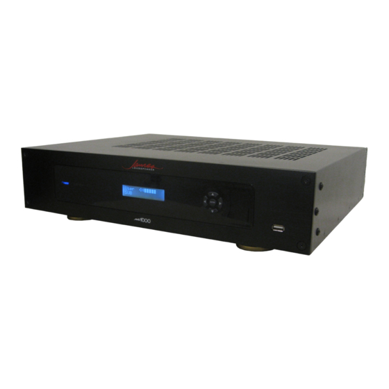
- Page 1 1000W (4/8 ohm and 70V) DSP SUBWOOFER AMPLIFIER USER MANUAL V1.8...
-
Page 2: Important Safety Instructions
IMPORTANT SAFETY INSTRUCTIONS 1. Read these instructions. 2. Keep these instructions. 3. Heed all warnings. 4. Follow all instructions. 5. Do not use this apparatus near water. 6. Clean only with a damp cloth. 7. Do not block any ventilation openings. Install in accordance with the manufacturer’s instructions. 8. -
Page 3: Installing Rack Mount Ears
Due to the weight of the M1000, it is recommended th at the rear flanges be secured to the rear rack rails. Hardware to do this is not supplied with the amplifier and is specific to the type and depth of rack you are using. - Page 4 Replace the plastic cover and screws over the voltage selector switch. The M1000 is fuse protected and if you change the AC voltage settlings, you also need to change the fuse to the correct value. Use only GDA type fuses. Values are listed below...
-
Page 5: Remote Control
Removing the binding post insulators Inserting banana plugs into wire holes If you haven’t done so, verify that the amplifier’s AC ma ins selector on the rear of the M1000 is set to your AC line voltage and you have the correct fuse installed. - Page 6 Standby Indicator - The word Standby will appear in red when the M1000 is in standby mode. The M1000 is put into Standby Mode by turning the amplifier off through either the remote, the auto off mode or the 12V trigger. Also, if the amplifier overheats, the standby indicator will come on as the amplifier will go into standby mode.
- Page 7 REAR PANEL Left/right high level inputs - for connecting high level speaker outputs from another amplifier to drive the subwoofer amplifier. Useful for zones where only stereo left/right high level speaker signals are available and a subwoofer needs to be added. Left/right RCA inputs - For feeding line-level stereo left/right signals.
-
Page 8: Lcd Display Screens/Functions
“External Trigger” ON “Limiter” ON Navigation through the DSP menus and DSP settings are done via the 5 button controller on the front of the M1000 and the 5 button array on the remote control. Once a limiter setting of anything but “0” is set, the red clip indicator on the front panel, which normally indicates full power clipping, will now light when the limiter maximum power is reached. - Page 9 Normal Screen This is the normal operating screen for the DSP and some of the current settings are displayed along with a volume bar and an output level bar meter. (see details above). NOTE: Pressing the Menu button will take you to the first DSP setting, “Subsonic Frequency”.
- Page 10 Crossover Slope ONLY AVAILABLE WHEN IN SUB MODE. This “Crossover Slope” setting allows the crossover slope to be set from 6 dB/octave 36 dB/octave in 6 dB/octave increments. The higher the slope, the less mid-band information will get through to the subwoofer, but there will be greater phase change which might effect the sound of the system as a whole.
- Page 11 But the actual power depends on the impedance of the load, so the limiter is set by -dB, which are independent of actual power but indicate level reductions. The load on the M1000 can be 1 or Limiter On 2 subwoofers, as long as the total impedance remains 4 ohms or higher.
- Page 12 Auto Off Setting The “Auto Off” setting allows the amplifier to turn on and off based on the presence of an audio signal. When set to “off”, the function is disabled and the amp stays on constantly. When set to ON, the amplifier is controlled by the presence, or absence, of audio signal on the input jacks.
-
Page 13: Default Settings
-30dB DSP MENU TREE Navigation through the display menus is Accomplished by the 5 button control pads on START/NORMAL SCREEN the front panel of the M1000. Adjusts volume 0 to -79 dB Sets subsonic filter from 16-40 Hz If no button is pressed for 3 seconds, the display reverts back to “normal”. - Page 14 0dB to -12dB, L i m i t e r . 0 d B 1 dB steps Feet, meters, D e l a y u n i t s msec m s e c . 0-30ft (or meters or msec) D e l a y m s e c .
-
Page 15: General Features
M1000: 1000W DSP SUBWOOFER 4/8 OHM and 70V AMPLIFIER SPECIFICATIONS GENERAL FEATURES - High Efficiency, Class D, 1000W RMS (4 ohms) output stage - DSP signal control for precise adjustment and configuration of the audio signal - 16x2 character LCD display... - Page 16 APPENDIX A – PRESET EQ CURVES To reprogram any Preset EQ, use the following settings 20 Hz 25 Hz 31 Hz 40 Hz 50 Hz 63 Hz 80 Hz 100 Hz 125 Hz Preset 1 0 dB 1 dB 1 dB 1 dB 0 dB 0 dB...
- Page 17 APPENDIX B – Thermal and Power Input Data THERMAL AND POWER INPUT DATA IDLE POWER, NO SIGNAL INPUT Voltage Watts Amps BTU'S Calories WATT = 3.41 BTU 0.277 29.92 71.61 18060 WATT = 860 Calories 0.291 33.47 78.43 19780 0.297 35.64 81.84 20640...
-
Page 18: Appendix C - Troubleshooting
5) NO OUTPUT ON THE RCA LOOP THROUGH RCA JACKS If you are feeding your signal into the XLR inputs, the initial production run of M1000’s did not feed the XLR outputs to the RCA loop out jacks. So you will need to use the RCA inputs for these models. This applies to any serial number starting with 0910. -
Page 19: Limited Warranty
LIMITED WARRANTY James Loudspeaker (“James”) warrants to the original retail purchaser (“Purchaser”) only that this James Product (the “Product”) is to be free from defects in materials and workmanship for a period as listed below for each product category: Indoor loudspeaker systems (excluding electronics) - (10) years Outdoor loudspeaker systems (excluding electronics) - (3) years Marine loudspeaker systems (excluding electronics) - (3) years Subwoofers (excluding electronic components) –...
Need help?
Do you have a question about the M1000 and is the answer not in the manual?
Questions and answers