Table of Contents
Advertisement
Quick Links
®
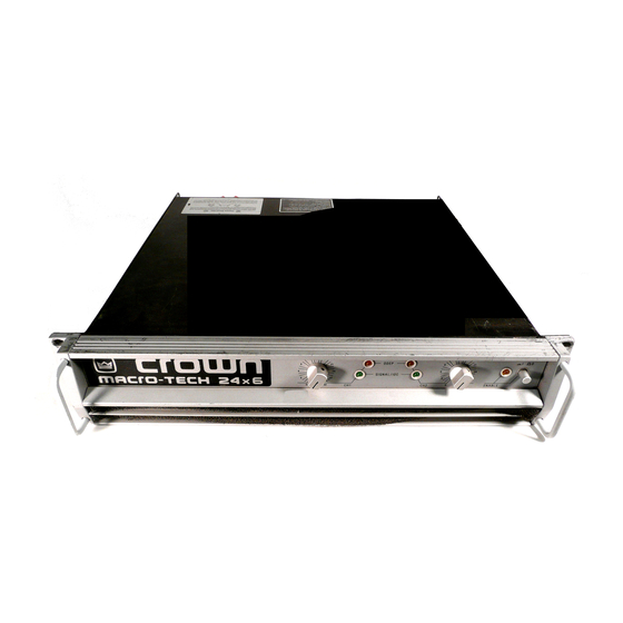
Models: Macro-Tech
24x6 & 36x12
Some models may be exported under the name Amcron .
®
© 2000 by Crown International, Inc., P.O. Box 1000, Elkhart, IN 46515-1000 U.S.A. Telephone: 219-294-
8000. Fax: 219-294-8329. Macro-Tech amplifiers are produced by the Professional Audio Division of Crown
International, Inc. Trademark Notice: SmartAmp,
™
Grounded Bridge
™
and PIP
™
are trademarks and
Amcron,
®
Crown ,
®
Macro-Tech ,
®
IOC ,
®
ODEP ,
®
IQ,
®
IQ System ,
®
and P.I.P.
®
are registered trademarks of
Crown International, Inc. Other trademarks are the property of their respective owners.
125782-3
3/00
Advertisement
Table of Contents

Related Manuals for Macro-Tech Macro-Tech 24x6


Summary of Contents for Macro-Tech Macro-Tech 24x6
- Page 1 Some models may be exported under the name Amcron . ® © 2000 by Crown International, Inc., P.O. Box 1000, Elkhart, IN 46515-1000 U.S.A. Telephone: 219-294- 8000. Fax: 219-294-8329. Macro-Tech amplifiers are produced by the Professional Audio Division of Crown International, Inc.
- Page 2 ITEMS EXCLUDED FROM THIS CROWN WARRANTY ITEMS EXCLUDED FROM THIS CROWN WARRANTY This Crown Warranty is in effect only for failure of a new Crown product which This Crown Warranty is in effect only for failure of a new Crown product occurred within the Warranty Period.
-
Page 3: Magnetic Field
If you need special assistance beyond the scope of this manual, please contact our Technical Support Group. Crown Audio Division Technical Support Group Plant 2 SW, 1718 W. Mishawaka Rd., Elkhart, Indiana 46517 U.S.A. Phone: 800-342-6939 (North America, Puerto Rico and Virgin Islands) or 219-294-8200 Fax: 219-294-8301 Fax Back (North America only): 800-294-4094 or 219-293-9200 Fax Back (International): 219-294-8100 Internet: http://www.crownaudio.com... -
Page 4: Important Safety Instructions
Macro-Tech ® 24x6 & 36x12 Power Amplifiers Important Safety Instructions 1) Read these instructions. 2) Keep these instructions 3) Heed all warnings. 4) Follow all instructions. 5) Do not use this apparatus near water. 6) Clean only with a dry cloth. 7) Do not block any ventilation openings. -
Page 5: Table Of Contents
Macro-Tech ® 24x6 & 36x12 Power Amplifiers CONTENTS 1 Welcome ................7 1.1 Unpacking ..............7 1.2 Features ............... 7 2 Facilities ................8 3 Installation ............... 10 3.1 Mounting ..............10 3.2 Cooling ..............10 3.3 Wiring ................ 11 3.3.1 Input Connection .......... - Page 6 Typical Damping Factor ............27 Typical Output Impedance ............27 Typical Phase Response ............28 Macro-Tech 24x6 Pwr Draw, Current Draw and Therm Dis ..28 Macro-Tech 36x12 Pwr Draw, Current Draw and Therm Dis ..29 Installing a PIP Module ............30 Installing a Level Control Shaft Lock ........
-
Page 7: Welcome
Only you, the consignee, may initiate a claim for 5-way binding post outputs provide versatile shipping damage. Crown will be happy to cooperate connection. fully as needed. Save the shipping carton as evidence Mounts in a standard 19-inch (48.3-cm) equipment... -
Page 8: Facilities
0.1 second hold delay if there is a differ- four seconds to protect your system from start-up tran- ence of 0.05% or more between the input and output sients. (This delay can be changed. Contact Crown’s signal waveforms. This provides proof of distortion-free Technical Support Group for details.) performance . -
Page 9: Rear Facilities
Macro-Tech ® 24x6 & 36x12 Power Amplifiers Fig. 2.2 Rear Facilities H. Reset Switches stalled (see Section 3.3.1). The phone jacks can also The reset switches are used to reset the breakers that be used as “daisy chain” outputs to simplify connecting safeguard each power supply from overload. -
Page 10: Installation
Macro-Tech ® 24x6 & 36x12 Power Amplifiers 3 Installation 3.1 Mounting When mounting the amplifier in a rack cabinet, the side Macro-Tech amplifiers are designed for standard 19 walls of the rack should be at least 2 inches (5 cm) away inch (48.3 cm) rack mounting as well as “stack”... -
Page 11: Wiring
3.3 Wiring This section describes the most common way to install two-channel operation. They do NOT offer mono opera- the Macro-Tech 24x6 and 36x12. Each model is de- tion. signed for biamplified systems and includes both a WARNING: Never strap the outputs together for Par- high-power and a medium-power channel. -
Page 12: Input Connection
Macro-Tech ® 24x6 & 36x12 Power Amplifiers 3.3.1 Input Connection Both the balanced XLR and phone jack inputs have a nominal impedance of 20 k ohms (10 k ohms with un- balanced wiring) and will accept the line-level output of most devices. -
Page 13: Subsonic Filter Capacitors
For balanced input wiring use one of the examples in Crown is not liable for personal injury or damage incurred when a transducer or component is over- Figure 3.10. Filters A, B and C correspond to the unbal- driven. -
Page 14: Output Connection
2,000 Consider the power-handling capacity of your load be- Wire (Ohms) 8000 fore connecting it to the amplifier. Crown is not liable for 1,000 5000 damage incurred at any time due to a load being over- Ohms/1000 Feet AWG (American... - Page 15 (Under these circumstances, cable tray or jacket. Crown’s IQ System ® is often used so amplifiers 4. Never connect the amplifier’s input and output can be monitored and controlled when they are grounds together.
-
Page 16: Additional Load Protection
Macro-Tech ® 24x6 & 36x12 Power Amplifiers Note: The components shown in Figure 3.12 are com- Typical fuses help prevent damage due to prolonged monly available from most electronic supply stores. overload, but provide essentially no protection against damage from large transients. To minimize this prob- 4-ohm, 20-watt lem, use high-speed instrument fuses such as the Resistor... -
Page 17: Operation
Fig. 4.1 Indicators outputs for Bridge-Mono operation! The limits the drive level of the output stages so the ampli- Macro-Tech 24x6 and 36x12 cannot be used in fier can continue safe operation even when conditions any mono mode. are severe. (For a more detailed description of ODEP, 2. -
Page 18: Protection Systems
This level of protection enables Crown to increase out- put efficiency to never-before-achieved levels while To do this, Crown established a rigorous program to greatly increasing amplifier reliability. -
Page 19: Standby Mode
Macro-Tech ® 24x6 & 36x12 Power Amplifiers It is very unlikely that you will ever see a Macro-Tech the drive level. Second, ODEP data is fed to the back amplifier activate transformer thermal protection as long panel PIP connector so advanced PIP modules like the as it is operated within rated conditions (see Section 6, IQ–P.I.P.–SMT can use it to monitor and control the am- Specifications ). -
Page 20: Filter Cleaning
26 dB. At 26 dB voltage gain, the equivalent input sensitivity is: Macro-Tech 24x6: 3.1 The Reset switches for the power supply circuit break- and 2.2 V for Channel 1 and 2, respectively. Macro-Tech ers are located on the back panel. -
Page 21: Technical Information
The amplifier is protected from all common hazards that VZ means Variable Impedance and is the name of plague high-power amplifiers, including shorted, open Crown’s patented articulated power supply technology. or mismatched loads; overloaded power supplies, ex- This technology is what makes it possible to pack such cessive temperature, chain-destruction phenomena, tremendous power into Crown’s Macro-Tech 3600VZ... -
Page 22: The Vz Supply
Macro-Tech ® 24x6 & 36x12 Power Amplifiers supply becomes larger, the power transistors must dis- When the voltage VZ POWER SUPPLY sipate more heat. Also, the lower the resistance of the requirements are power transistors, the more voltage you can deliver to high, VZ supplies POWER the load. - Page 23 Macro-Tech ® 24x6 & 36x12 Power Amplifiers nal from the gain pot, and drives the voltage translator bridge-balanced output stage. stage. The protection mechanisms that affect the signal path The voltage translator stage channels the signal to the are implemented to protect the amplifier under real- Last Voltage Amplifiers (LVAs), depending on the sig- world conditions.
-
Page 24: Circuit Block Diagram
Macro-Tech ® 24x6 & 36x12 Power Amplifiers Fig. 5.5 Circuit Block Diagram (Channel 1) Page 24 Reference Manual... -
Page 25: Specifications
420 watts into 4 ohms. set to 0.775 V as listed below: 285 watts into 8 ohms. Macro-Tech 24x6 Channel 1 (2400): 83:1 ±12% or 38 dB ±0.5 dB. It is extremely important to have adequate AC power available. Power amplifiers cannot create energy—they Macro-Tech 24x6 Channel 2 (600): 54:1 ±12% or 35 dB... - Page 26 6 inches (15 cm) behind the front mounting surface. 8 for information on optional PIP modules). Macro-Tech 24x6: 45 lbs, 4 oz. (20.5 kg). Shipping weight is 54 lbs, 11 oz. (24.8 kg). Input Impedance: Nominally 20 k ohms, balanced.
-
Page 27: Typical Frequency Response
Macro-Tech ® 24x6 & 36x12 Power Amplifiers Fig. 6.1 Typical Frequency Response Fig. 6.2 Typical Damping Factor Fig. 6.3 Typical Output Impedance Reference Manual Page 27... -
Page 28: Typical Phase Response
24x6 & 36x12 Power Amplifiers +45˚ 0˚ –45˚ TECHRON TEF ® 10 K 20 K FREQUENCY (Hz) Fig. 6.4 Typical Phase Response Fig. 7.1 Macro-Tech 24x6 Power Draw, Current Draw and Thermal Dissipation at Various Duty Cycles Page 28 Reference Manual... -
Page 29: Ac Power Draw & Heat Dissipation
Here are the equations used to calculate the data pre- sented in Figures 7.1 and 7.2: amount of power and current drawn from the AC mains by the Macro-Tech 24x6 and 36x12 amplifiers and the Total output power will all x Duty amount of heat produced under various conditions. -
Page 30: Accessories
Processor with DSP (Digital Signal Processing) for PIP- compatible amplifiers. As a component of the IQ System, it connects the amplifier to the Crown Bus so the amplifier can be controlled and monitored. Its DSP capabilities enable it to be programmed with a variety of functions, ∞... - Page 31 C H - 1 Input Processor (P.I.P.) P.I.P.-BP1C The P.I.P.-BP1C is a versatile, stereo band-pass processor that plugs into any PIP-capable Crown amplifier. P.I.P.-PA permits the unique capability of adding one mic/ Each channel of the P.I.P.-BP1C is completely independent line input directly to each channel of an amplifier.
-
Page 32: Level Control Security Kit
They can be ordered through secure your amplifier’s level controls in situations where the Crown Service/Parts Department. For more informa- the front panel controls are subject to tampering. One is tion, contact the Crown Service Department. -
Page 33: Service
This method usually saves the most time and effort. Sim- ply present your bill of sale along with the defective unit If you have any questions, please call or write the Crown to an authorized service center to obtain service. They Technical Support Group. - Page 34 Crown Factory Service Information Shipping Address: Crown International, Inc., Factory Service, Plant 2 SW, 1718 W. Mishawaka Rd., Elkhart, IN 46517 Phone: 1-800-342-6939 or 1-219-294-8200 Fax: 1-219-294-8124 Owner’s Name: _________________________________________________________________________ Shipping Address: ______________________________________________________________________ Phone Number: _____________________________ Fax Number: _____________________________ Model: ________________________ Serial Number: ______________ Purchase Date: ___________ NATURE OF PROBLEM (Be sure to describe the conditions that existed when the problem occurred and what attempts were made to correct it.)
Need help?
Do you have a question about the Macro-Tech 24x6 and is the answer not in the manual?
Questions and answers