Table of Contents
Advertisement
INSTRUCTION MANUAL
GUIDE D'UTILISATION
MANUAL DE INSTRUCCIONES
DXCMLA1682066
Single Stage, Belt Drive, Electric Air Compressors
Compresseurs d'air électriques à un étage à entraînement par courroie
Compresores eléctricos de aire, de una sola etapa y accionamiento por correa
If you have questions or comments, contact us.
Pour toute question ou tout commentaire, nous contacter.
Si tiene dudas o comentarios, contáctenos.
1-888-895-4549 • www.dewalt.com
INSTRUCTIVO DE OPERACIÓN, CENTROS DE SERVICIO Y
PÓLIZA DE GARANTÍA. ADVERNTENCIA: LÉASE ESTE
INSTRUCTIVO ANTES DE USAR EL PRODUCTO.
Advertisement
Table of Contents

Related Manuals for DeWalt DXCMLA1682066


Summary of Contents for DeWalt DXCMLA1682066
- Page 1 If you have questions or comments, contact us. Pour toute question ou tout commentaire, nous contacter. Si tiene dudas o comentarios, contáctenos. 1-888-895-4549 • www.dewalt.com INSTRUCTION MANUAL INSTRUCTIVO DE OPERACIÓN, CENTROS DE SERVICIO Y GUIDE D'UTILISATION PÓLIZA DE GARANTÍA. ADVERNTENCIA: LÉASE ESTE INSTRUCTIVO ANTES DE USAR EL PRODUCTO.
-
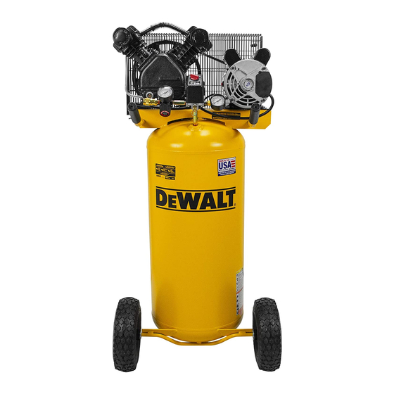
Page 2: Air Compressor
2 Cylinder Single Stage Oil Lubricated Cast iron crankcase, cylinder, and aluminum head Weight: 30.5 lbs (13.8 kg.) Oil Capacity: 11.35 oz. (336 mL) Specifications MODEL DXCMLA1682066 WEIGHT 159 lbs. (72 kg) HEIGHT 50.12" WIDTH 24.12" AIR TANK CAPACITY 20 gallons (75,7 liters) APPROX. -
Page 3: Hot Surfaces
Hot Surfaces Definitions: Safety Guidelines COMPRESSOR CYLINDER The definitions below describe the level of severity FIG. 2 & HEAD for each signal word. Please read the manual and pay atten- tion to these symbols. PUMP DANGER: Indicates an imminently hazardous situation CRANKCASE which, if not avoided, will result in death or serious injury. - Page 4 SAVE THESE INSTRUCTIONS • Unattended operation of this • Always remain in attendance product could result in per- with the product when it is sonal injury or property dam- operating. age. To reduce the risk of • Always turn off and unplug fire, do no allow the com- unit when not in use. DANGER: RISK OF EXPLOSION OR FIRE pressor to operator unat- tended...
- Page 5 • Unauthorized modifications to • The air tank is designed the safety valve, or any other to withstand specific components which control air operating pressures. Never tank pressure. make adjustments or parts DANGER: RISK OF BURSTING substitutions to alter the factory Air Tank: On February 26, 2002, the U.S. Consumer Product Safety set operating pressures.
- Page 6 WARNING: RISK FROM FLYING OBJECTS DANGER: RISK OF INJURY OR PROP ER TY DAMAGE WHEN TRANSPORTING OR STORING WHAT CAN HAPPEN HOW TO PREVENT IT WHAT CAN HAPPEN HOW TO PREVENT IT • The compressed air stream • Always wear certified safety • Oil can leak or spill and could • Always place compressor can cause soft tissue damage equipment: ANSI Z87.1 eye...
- Page 7 • Repairs attempted by • Any electrical wiring or unqualified personnel can repairs required on this result in serious injury or product should be per- death by electrocution. formed by authorized ser- WARNING: RISK OF HOT SURFACES vice center personnel in WHAT CAN HAPPEN HOW TO PREVENT IT accordance with national • Touching exposed metal such • Never touch any exposed...
- Page 8 WARNING: RISK FROM MOVING PARTS WARNING: RISK OF UNSAFE OPERATION WHAT CAN HAPPEN HOW TO PREVENT IT WHAT CAN HAPPEN HOW TO PREVENT IT • Moving parts such as the • Never operate the compressor pulley, flywheel, and belt can with guards or covers which are • Unsafe op e r a t ion of your air • Review and understand all compressor could lead to se ri- instructions and warnings in...
-
Page 9: Know Your Air Compressor
Know Your Air Compressor READ THIS OWNER’S MANUAL AND SAFETY RULES BEFORE OPERATING YOUR UNIT. Compare the illustrations with your WARNING: RISK OF INJURY FROM LIFTING unit to familiarize yourself with the location of various controls and adjustments. Save this manual for future reference. WHAT CAN HAPPEN HOW TO PREVENT IT FEATURES... - Page 10 reaches cut-out pressure, the check valve closes, allowing air automotive, and ARO. One hand push-to-connect operation makes pressure to remain inside the air tank. connections simple and easy. AIR INTAKE FILTERS REGULATOR The filters (A) are designed to clean air entering the The regulator knob (E) controls the air pressure coming from the air pump.
-
Page 11: Installation
INSTALLATION Lubrication and Oil Assembly (Fig. 1) AIR COMPRESSOR The air compressor pump was filled WITH oil at the manufacturer. Unpack the air compressor. Inspect the unit for damage. If the Check air compressor pump oil level before operating unit. See unit has been damaged in transit, contact the carrier and Compressor Pump Oil under Maintenance. -
Page 12: Wiring Instructions
Grounding Instructions temperature changes. Two signs of excessive humidity are external condensation on the pump when it cools down and a “milky” WARNING: Risk of electrical shock. In the event of a short appearance in compressor oil. You may be able to prevent circuit, grounding reduces the risk of shock by providing an escape moisture from forming in the pump by increasing ventilation or wire for the electric current. -
Page 13: Voltage And Circuit Protection
• a 3wire extension cord that has a 3blade grounding plug, and change the cord set. a 3-slot receptacle that will accept the plug on the product How to Use Your Unit (Fig 3) • in good condition • plug is not worn How to Stop: • no longer than 50 feet (15.2 m) Set the Auto/Off switch to “Off”. • 12 gauge (AWG) or larger. (Wire size increases as gauge number Before Starting decreases. -
Page 14: Before Each Start-Up
NOTE: After about 30 minutes, If the unit does not operate WARNING: Risk of bursting. Too much air pressure causes a properly, SHUT DOWN IMMEDIATELY, and contact hazardous risk of bursting. Check the manufacturer’s maximum Product Service. pressure rating for air tools and accessories. The regulator outlet Check all air line fittings and connections/piping for air leaks pressure must never exceed the maximum pressure rating. -
Page 15: Maintenance Chart
MAINTENANCE 4. Drain the air tank, see Draining Air Tank under Maintenance. Ensure air tank pressure gauge reads 0 psi. Maintenance Chart WARNING: Risk of bursting. Drain air tank daily. Water will condense in air tank. If not drained, water will corrode and weaken Procedure the air tank causing a risk of air tank rupture. - Page 16 Checking Air Filter (Fig. 1) WARNING: Risk of unsafe operation. Unit cycles automati- cally when power is on. When performing maintenance, you may WARNING: Hot surfaces. Risk of burn. Tubes, pump head, and be exposed to voltage sources, compressed air, or moving parts. surrounding parts are very hot, do not touch (see the Hot Surfaces Personal injuries can occur.
- Page 17 condensate contains lubricating oil and/or substances which may be Checking regulated and must be disposed of in accordance with local, state, The oil level should be to the middle of the sight glass (X). and federal laws and regulations. If needed remove oil fill plug (Y) and slowly add oil until it Set the Auto/Off switch to “Off”.
-
Page 18: Belt Replacement
Mark motor position on U = Full saddle. V = Add S = Oil drain plug Loosen motor T = Oil level sight glass mounting screws and R = Oil fill plug slide the motor toward the air compressor. Remove the belt and replace with a new one. -
Page 19: Motor Pulley/Flywheel Alignment
within 1/16” (1.6 mm) to prevent excessive belt wear. Verify the should appear to be equal. If they are not, loosen the setscrew alignment by performing the following Motor Pulley/Flywheel - of the motor drive pulley and equalize B1 and B2, using care Alignment. -
Page 20: To Replace Or Clean Check Valve
Carefully move pressure relief tube away from check need assistance in locating any accessory for your tool, please call valve. 1-888-895-4549 or visit our website www.dewalt.com. Unscrew the check WARNING: The use of any other accessory not recommended valve (turn counter- for use with this tool could be hazardous. -
Page 21: Limited Warranty
This environmental conditions, cosmetic defects, and routine warranty also does not apply to merchandise sold by DEWALT maintenance items, are specifically excluded from this warranty. which has been manufactured by and identified as the Routine maintenance items such as: oil, lubricants, and air filters, product of another company, such as gasoline engines. -
Page 22: Troubleshooting Guide
• Labor, service calls, and travel charges, are not covered • All other parts 30 days after the first year of ownership on stationary • No return authorization will be issued for electrical compressors (compressors without handles, or wheels). components once items are installed. Repairs requiring overtime, weekend rates, or any other How do You Get Service? In order to be eligible for service charges beyond the standard shop labor rate are not under this warranty you must be the original retail purchaser, covered. - Page 23 GLOSSARY or your dealer. CFM: Cubic feet per minute. Problem SCFM: Standard cubic feet per minute; a unit of measure of air delivery. FREE WARNING LABEL REPLACEMENT: If your warning labels PSI: Pounds per square inch; a unit of measure of pressure. become illegible or are missing, call 1-888-895-4549 for a free replacement.
- Page 24 Code Air leaks ............................ 1 Air leaks in air tank or at air tank welds ..................2 Air leaks between head and valve plate ..................3 Air leaks from safety valve ......................4 Compressor is not supplying enough air to operate accessories ..........1, 5, 6, 7, 9, 10 Restricted air intake.
-
Page 25: Troubleshooting Codes
Troubleshooting Codes CODE POSSIBLE CAUSE POSSIBLE SOLUTION Fittings are not tight Tighten fittings where air can be heard escaping. Check fittings with soapy water solution. DO NOT OVERTIGHTEN. Defective air tank Air tank must be replaced. Do not repair the leak. WARNING: Risk of bursting. - Page 26 CODE POSSIBLE CAUSE POSSIBLE SOLUTION Carbon build-up in pump Contact a D WALT factory service center or a D WALT authorized service center. Belt to tight Check belt tension, see Adjusting Belt Tension under Maintenance. Pulley misalignment See Motor Pulley/Flywheel Alignment under Maintenance. Pump oil is low Add synthetic blend, non-detergent air compressor oil to pump.
- Page 27 CODE POSSIBLE CAUSE POSSIBLE SOLUTION Damaged regulator Replace Regulator open Roate the regulator knob counter-clockwise to its built-in stop. Low voltage/motor overload Check that power supply is adequate and that compressor is on a dedicated circuit. If using extension cord, try using without. If compressor is connected to a circut protected by a fuse, use dual element time delay fuses (Buss Fusetron type “T”...
- Page 28 WALT Industrial Tool Co. The following are trademarks for one or more DEWALT power tools: thee yellow and black color scheme; the “D” shaped air intake grill; the array of pyramids on the handgrip; the kit box configuration; and the array of lozenge shape humps on the surface of the tool.
Need help?
Do you have a question about the DXCMLA1682066 and is the answer not in the manual?
Questions and answers