
Related Manuals for DeWalt DXCMTA1980854


Summary of Contents for DeWalt DXCMTA1980854
- Page 1 If you have questions or comments, contact us. 1-888-895-4549 • www.dewalt.com INSTRUCTION MANUAL DXCMTA1980854 Single Stage, Belt Drive, Electric Air Compressors...
-
Page 2: Pump Specifications
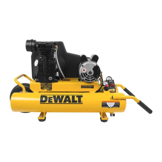
Air Compressor MODEL DXCMTA1980854 A. Pump Air Intake Filter 175 psi APPROX. BLOW OFF PRESSURE B. Auto(-)/Off(O) Switch C. Air Tank Pressure Gauge D. Regulated Pressure Gauge E. Pressure Regulator F. Air Outlet FIG. 1 G. Safety Valve H. Air Tank Drain Valve Pump Oil Fill Plug J. -
Page 3: Hot Surfaces
Hot Surfaces Definitions: Safety Guidelines COMPRESSOR CYLINDER The definitions below describe the level of severity & HEAD FIG. 2 for each signal word. Please read the manual and pay attention OUTLET TUBE to these symbols. PUMP DANGER: Indicates an imminently hazardous situation CRANKCASE which, if not avoided, will result in death or serious injury. - Page 4 SAVE THESE INSTRUCTIONS • Unattended operation of this • Always remain in attendance product could result in per- with the product when it is sonal injury or property dam- operating. age. To reduce the risk of • Always turn off and unplug fire, do no allow the com- unit when not in use.
- Page 5 • Unauthorized modifications to • The air tank is designed the safety valve, or any other to withstand specific components which control air operating pressures. Never tank pressure. make adjustments or parts DANGER: RISK OF BURSTING substitutions to alter the factory Air Tank: On February 26, 2002, the U.S.
- Page 6 DANGER: RISK OF INJURY OR PROP ER TY DAMAGE WHEN TRANSPORTING OR STORING WHAT CAN HAPPEN HOW TO PREVENT IT • Oil can leak or spill and could • Always place compressor result in fire or breathing on a protective mat when hazard;...
- Page 7 • Repairs attempted by • Any electrical wiring or unqualified personnel can repairs required on this result in serious injury or product should be per- death by electrocution. formed by authorized ser- WARNING: RISK OF HOT SURFACES vice center personnel in WHAT CAN HAPPEN HOW TO PREVENT IT accordance with national...
- Page 8 WARNING: RISK FROM MOVING PARTS WARNING: RISK OF UNSAFE OPERATION WHAT CAN HAPPEN HOW TO PREVENT IT WHAT CAN HAPPEN HOW TO PREVENT IT • Moving parts such as the • Never operate the compressor pulley, flywheel, and belt can with guards or covers which are •...
-
Page 9: Know Your Air Compressor
Know Your Air Compressor READ THIS OWNER’S MANUAL AND SAFETY RULES BEFORE OPERATING YOUR UNIT. Compare the illustrations with your WARNING: RISK OF INJURY FROM LIFTING unit to familiarize yourself with the location of various controls and adjustments. Save this manual for future reference. WHAT CAN HAPPEN HOW TO PREVENT IT FEATURES... - Page 10 reaches cut-out pressure, the check valve closes, allowing air automotive, and ARO. One hand push-to-connect operation makes pressure to remain inside the air tank. connections simple and easy. AIR INTAKE FILTER REGULATOR The filter (A) is designed to clean air entering the The regulator knob (E) controls the air pressure coming from the air pump.
- Page 11 Deciding the best mode of operation is as simple as determining the INSTALLATION amount of time the compressor will be required to supply air. Assembly (Fig. 1) If the air needed is infrequent, turn the adjustment knob on top of the Unpack the air compressor.
-
Page 12: Wiring Instructions
Lubrication and Oil temperature changes. Two signs of excessive humidity are external condensation on the pump when it cools down and a “milky” AIR COMPRESSOR appearance in compressor oil. You may be able to prevent The air compressor pump was filled WITH oil at the manufacturer. moisture from forming in the pump by increasing ventilation or Check air compressor pump oil level before operating unit. -
Page 13: Grounding Instructions
Grounding Instructions a 3-slot receptacle that will accept the plug on the product • in good condition WARNING: Risk of electrical shock. In the event of a short circuit, • plug is not worn grounding reduces the risk of shock by providing an escape wire for the electric current. - Page 14 properly, SHUT DOWN IMMEDIATELY, and contact Product Service. How to Use Your Unit (Fig 3) Check all air line fittings and connections/piping for air leaks How to Stop: by applying a soap solution. Correct if necessary. NOTE: Minor leaks can cause the air compressor to overwork, resulting in Set the Auto/Off switch to “Off”.
- Page 15 WARNING: Risk of unsafe operation. Firmly grasp air hose in hand WARNING: Risk of bursting. Too much air pressure causes a when installing or disconnecting to prevent hose whip. hazardous risk of bursting. Check the manufacturer’s maximum pressure rating for air tools and accessories. The regulator outlet 4.
-
Page 16: Maintenance Chart
MAINTENANCE WARNING: Risk of unsafe operation. Unit cycles automati- cally when power is on. When performing maintenance, you may Maintenance Chart be exposed to voltage sources, compressed air, or moving parts. Procedure Personal injuries can occur. Before performing any maintenance or repair, disconnect power source from the compressor and bleed off all air pressure. - Page 17 Checking Air Filter (Fig. 1) regulated and must be disposed of in accordance with local, state, and federal laws and regulations. WARNING: Hot surfaces. Risk of burn. Tubes, pump head, and Set the Auto/Off switch to “Off”. surrounding parts are very hot, do not touch (see the Hot Surfaces Pull the regulator knob out and turn counterclockwise to set the identified in Fig.
-
Page 18: Belt Replacement
Checking V = Full The oil level should be to the middle of the sight glass (T). W = Add If needed remove oil fill plug (U) and slowly add oil until it S = Oil drain plug T = Oil level sight glass reaches the middle of the sight glass. -
Page 19: Adjusting Belt Tension
all four motor mounting screws. Torque to 20-25 ft-lbs Remove the belt guard by (27.1–33.9 Nm). removing the 5 screws NOTE: Once the engine pulley has been moved from its factory set (X) using a Phillips head screwdriver. location, the grooves of the flywheel and pulley must be aligned to within 1/16”... -
Page 20: Air Compressor Pump Intake And Exhaust Valves
Service and Adjustments ments are within 1/16” (1.6 mm) of each other. Tighten the motor drive pulley set screw. ALL MAINTENANCE AND REPAIR OPERATIONS NOT LISTED Visually inspect the motor drive pulley to verify that it is per- MUST BE PERFORMED BY TRAINED SERVICE TECHNICIAN. pendicular to the drive motor shaft. -
Page 21: Additional Service
This warranty Recommended accessories for use with your tool are available for also does not apply to merchandise sold by DEWALT which has purchase from your local dealer or authorized service center. If you... - Page 22 and labor to remedy substantial defects due to materials • Labor, service calls, and travel charges, are not covered and workmanship during the first year of ownership, with the after the first year of ownership on stationary exceptions noted below. Parts used in repair of whole goods or compressors (compressors without handles, or wheels).
- Page 23 • All other parts 30 days FREE WARNING LABEL REPLACEMENT: If your warning labels become illegible or are missing, call 1-888-895-4549 for a free • No return authorization will be issued for electrical replacement. components once items are installed. How do You Get Service? In order to be eligible for service under this warranty you must be the original retail purchaser, and provide proof of purchase from one of the Company’s dealers, distributors, or retail outlet stores.
- Page 24 GLOSSARY the components are manufactured, tested and inspected to the specifications set by ASME. CFM: Cubic feet per minute. CSA: Canadian Standards Association SCFM: Standard cubic feet per minute; a unit of measure of air Indicates that the products that have this marking have delivery.
-
Page 25: Troubleshooting Guide
Troubleshooting Guide This section provides a list of the more frequently encountered malfunctions, their causes and corrective actions. The operator or maintenance personnel can perform some corrective actions, and others may require the assistance of a qualified D WALT technician or your dealer. -
Page 26: Troubleshooting Codes
Troubleshooting Codes CODE POSSIBLE CAUSE POSSIBLE SOLUTION Fittings are not tight Tighten fittings where air can be heard escaping. Check fittings with soapy water solution. DO NOT OVERTIGHTEN. Defective air tank Air tank must be replaced. Do not repair the leak. WARNING: Risk of bursting. - Page 27 CODE POSSIBLE CAUSE POSSIBLE SOLUTION Carbon build-up in pump Contact a D WALT factory service center or a D WALT authorized service center. Belt to tight Check belt tension, see Adjusting Belt Tension under Maintenance. Pulley misalignment See Motor Pulley/Flywheel Alignment under Maintenance. Pump oil is low Add synthetic blend, non-detergent air compressor oil to pump.
- Page 28 CODE POSSIBLE CAUSE POSSIBLE SOLUTION Regulator open Rotate the regulator knob counter-clockwise to its built-in stop and push knob in to lock in place. Low voltage/motor overload Check that power supply is adequate and that compressor is on a dedicated circuit. If using extension cord, try using without. If compressor is connected to a circut protected by a fuse, use dual element time delay fuses (Buss Fusetron type “T”...
- Page 29 WALT Industrial Tool Co. The following are trademarks for one or more DEWALT power tools: thee yellow and black color scheme; the “D” shaped air intake grill; the array of pyramids on the handgrip; the kit box configuration; and the array of lozenge shape humps on the surface of the tool.
Need help?
Do you have a question about the DXCMTA1980854 and is the answer not in the manual?
Questions and answers