Table of Contents
Advertisement
Quick Links
Title:
Revision:
Revision Date:
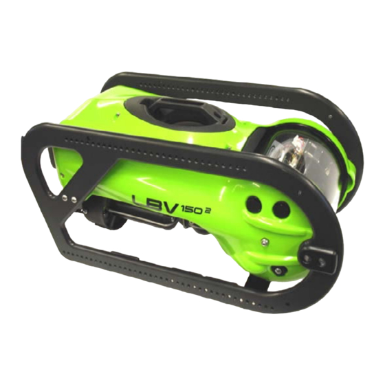
LBV150
B
27 Jan 10
Document Number:
DOCS- 001
©2009 SeaBotix Inc., all rights reserved
User's Manual
Proprietary Notice:
Words and logos marked with ® or ™ are registered trademarks or trademarks of their respective owners. No license under any copyright,
trademark, patent or other intellectual property right of SeaBotix or any third party are granted by implication in connection therewith. This
Document is being furnished in confidence by SeaBotix Inc. This Document and the information disclosed herein are proprietary data of
SeaBotix Inc. Neither this Document nor the information contained within shall be used, reproduced, or disclosed to third parties without the
express written authorization of SeaBotix Inc. Use of this Document for other than the intended purpose is strictly prohibited.
Head Office: SeaBotix Inc., 2877 Historic Decatur Road STE 100, San Diego, CA 92106 USA +1 (619) 450-4000
Australia Office: SeaBotix Australia Pty Ltd.8A Sparks Road, Henderson, WA 6166, Australia +61 (0)8 9437-5400
Advertisement
Table of Contents
Troubleshooting

Related Manuals for SeaBotix LBV150

Summary of Contents for SeaBotix LBV150
- Page 1 User’s Manual Proprietary Notice: Words and logos marked with ® or ™ are registered trademarks or trademarks of their respective owners. No license under any copyright, trademark, patent or other intellectual property right of SeaBotix or any third party are granted by implication in connection therewith. This Document is being furnished in confidence by SeaBotix Inc. This Document and the information disclosed herein are proprietary data of SeaBotix Inc. Neither this Document nor the information contained within shall be used, reproduced, or disclosed to third parties without the express written authorization of SeaBotix Inc. Use of this Document for other than the intended purpose is strictly prohibited. Head Office: SeaBotix Inc., 2877 Historic Decatur Road STE 100, San Diego, CA 92106 USA +1 (619) 450-4000 Australia Office: SeaBotix Australia Pty Ltd.8A Sparks Road, Henderson, WA 6166, Australia +61 (0)8 9437-5400 ...
-
Page 2: Table Of Contents
Table of Contents Using this manual .................... 5 Purpose of this manual ................... 5 Confidential Information ................. 6 Proprietary Notice ................... 6 International Hazard Symbol ................6 Other safety symbols ..................7 Safety Overview ....................7 General Safety Overview................. 7 Summary of Danger, Warning and Caution Safety Messages ..... - Page 3 2.1.5 TRIM ..................... 21 2.1.6 AUTO HEAD ................. 21 2.1.7 AUTO DEPTH ................21 2.1.8 CAMERA ..................22 2.1.9 TILT ....................22 2.1.10 FOCUS ..................22 2.1.11 LIGHT ................... 22 2.1.12 POWER ..................22 2.1.13 POSITION ..................22 2.1.14 ACCESSORIES ................23 2.1.15 KEYPAD ..................
- Page 4 Section 4: Maintenance ................37 After each use ................37 4.1.1 After each use – dirty water conditions ......... 37 4.1.2 Every 50 hours ................41 Every 500 hours ................43 Long term ..................43 Repairs ..................43 Software ..................44 Optional Components ..............
-
Page 5: Using This Manual
Throughout this manual information of special interest is highlighted with the following symbols. Be sure to read and understand each of these important messages. Page 5 of 64 DOCS-001 Manual, SeaBotix Inc. Users, 150 – 200 Series - Rev B – 27 Jan 10 -... -
Page 6: Confidential Information
Product Safety Information in Product Manuals, Instructions, and Other Collateral Materials, is consistent with the ISO 7010 General Warning Sign. Page 6 of 64 DOCS-001 Manual, SeaBotix Inc. Users, 150 – 200 Series - Rev B – 27 Jan 10 -... -
Page 7: Other Safety Symbols
Every effort has been made to ensure personnel safety at all times. Failure to comply with all safety messages and instructions may result in personal injury or equipment damage. Page 7 of 64 DOCS-001 Manual, SeaBotix Inc. Users, 150 – 200 Series - Rev B – 27 Jan 10 -... -
Page 8: Summary Of Danger, Warning And Caution Safety Messages
LBV system that has been altered or modified without the prior written consent from SeaBotix, Inc. Page 8 of 64 DOCS-001 Manual, SeaBotix Inc. Users, 150 – 200 Series - Rev B – 27 Jan 10 -... -
Page 9: Thruster Propellers
LBV and/or alter any documentation at any time, without notice, or may alter any or all documentation without notice. Page 9 of 64 DOCS-001 Manual, SeaBotix Inc. Users, 150 – 200 Series - Rev B – 27 Jan 10 -... -
Page 10: Section 1: Introduction
Note: When unpacking the LBV after receipt, inspect the LBV for damage. It is strongly recommended that vacuum be verified before each use (see section 1.4.1.4, page 14). Page 10 of 64 DOCS-001 Manual, SeaBotix Inc. Users, 150 – 200 Series - Rev B – 27 Jan 10 -... -
Page 11: Power Requirements
Step 2 Put a small amount of silicone lubricant (GLA001 which is supplied with your order) on your finger. Page 11 of 64 DOCS-001 Manual, SeaBotix Inc. Users, 150 – 200 Series - Rev B – 27 Jan 10 -... - Page 12 Once the tether is connected to the LBV, the next step is to connect the Integrated Control Console. Again be careful that the Integrated Control Console is OFF. Page 12 of 64 DOCS-001 Manual, SeaBotix Inc. Users, 150 – 200 Series - Rev B – 27 Jan 10 -...
-
Page 13: Integrated Control Console
This process should be done each time the LBV is operated and will only take a moment to perform. Page 13 of 64 DOCS-001 Manual, SeaBotix Inc. Users, 150 – 200 Series - Rev B – 27 Jan 10 -... -
Page 14: Inspection
Pull vacuum to 10 inches of mercury and hold for 10 minutes (watch for loss of vacuum). The gauge should read the same after 10 minutes. Page 14 of 64 DOCS-001 Manual, SeaBotix Inc. Users, 150 – 200 Series - Rev B – 27 Jan 10 -... -
Page 15: Powering Up The System
2. Push the joystick left then right to ensure that the lateral thruster operates correctly. 3. Rotate the joystick left then right to ensure that the forward thrusters operate correctly. Page 15 of 64 DOCS-001 Manual, SeaBotix Inc. Users, 150 – 200 Series - Rev B – 27 Jan 10 -... -
Page 16: Camera(S)
1. If fitted with accessories such as a grabber (page 25 section 2.3.1) and test and the keys to ensure that the grabber closes and opens. Page 16 of 64 DOCS-001 Manual, SeaBotix Inc. Users, 150 – 200 Series - Rev B – 27 Jan 10 -... -
Page 17: Post Dive Inspection
NOTE: If the LBV is positively buoyant or negatively buoyant, the vertical thruster and the auto depth function will not be as effective or may not work at all. Page 17 of 64 DOCS-001 Manual, SeaBotix Inc. Users, 150 – 200 Series - Rev B – 27 Jan 10 -... -
Page 18: Calibrating Compass
LBV does not pitch up or down. Access the calibration menu as follows: • Press PGRM • Press 5 (Main Menu) • Press 2 (Calibrate) • Press 4 (Compass) Page 18 of 64 DOCS-001 Manual, SeaBotix Inc. Users, 150 – 200 Series - Rev B – 27 Jan 10 -... - Page 19 LBV be used in a different geographic location, re-calibration may be required. It is good practice to calibrate the compass whenever time allows. Page 19 of 64 DOCS-001 Manual, SeaBotix Inc. Users, 150 – 200 Series - Rev B – 27 Jan 10 -...
-
Page 20: Section 2: Lbv Controls
The control knob is variable and has a center detent turning the vertical thruster off. Ensure that the vertical thruster is off prior to removing the LBV from the water. Page 20 of 64 DOCS-001 Manual, SeaBotix Inc. Users, 150 – 200 Series - Rev B – 27 Jan 10 -... -
Page 21: Vertical Gain
DEPTH button and the LBV will maintain the depth. An LED above the button will illuminate to illustrate that the Auto Depth is on as well as a “*” Page 21 of 64 DOCS-001 Manual, SeaBotix Inc. Users, 150 – 200 Series - Rev B – 27 Jan 10 -... -
Page 22: Camera
The POWER button allows the user to power up the LBV. A red LED will illuminate when the LBV is powered up. 2.1.13 POSITION Page 22 of 64 DOCS-001 Manual, SeaBotix Inc. Users, 150 – 200 Series - Rev B – 27 Jan 10 -... -
Page 23: Accessories
Pressing the PRGM key will access the menu screens. Use the numbers to select the desired option. See the Menus (page 21, section 2.3) for more information. Page 23 of 64 DOCS-001 Manual, SeaBotix Inc. Users, 150 – 200 Series - Rev B – 27 Jan 10 -... -
Page 24: Video Overlay
9. Selected Accessory 4. Heading 10. Depth & Reference 5. Turns Counter 11.Temperature & Reference 6. Camera Angle 12.Time Page 24 of 64 DOCS-001 Manual, SeaBotix Inc. Users, 150 – 200 Series - Rev B – 27 Jan 10 -... -
Page 25: Video Overlay Description
To change the display and calibrate, see the Menu section (page 28, section 2.3.4.3). A “*” will appear next to the heading or depth if the corresponding Auto function is on. Page 25 of 64 DOCS-001 Manual, SeaBotix Inc. Users, 150 – 200 Series - Rev B – 27 Jan 10 -... -
Page 26: Camera Angle
There can be up to 28 characters displayed at the top of the screen (1). To input the characters refer to the Menu section (page 27, section 2.3.3.4) Page 26 of 64 DOCS-001 Manual, SeaBotix Inc. Users, 150 – 200 Series - Rev B – 27 Jan 10 -... -
Page 27: Menus
Pressing the 3 key will take you to the Diagnostics Main Menu. 4. Options a. Pressing the 4 key will take you to the Options Main Menu. Page 27 of 64 DOCS-001 Manual, SeaBotix Inc. Users, 150 – 200 Series - Rev B – 27 Jan 10 -... -
Page 28: Setup Menu
This menu is used to set the display type used with the LBV. 1. NTSC/PAL M/N 2. PAL B/G 3. PAL I 4. PAL D/K Page 28 of 64 DOCS-001 Manual, SeaBotix Inc. Users, 150 – 200 Series - Rev B – 27 Jan 10 -... -
Page 29: Calibrate Menu
Return them to normal, calibrate the tilt, and then if desired set them to reverse after completion. Page 29 of 64 DOCS-001 Manual, SeaBotix Inc. Users, 150 – 200 Series - Rev B – 27 Jan 10 -... - Page 30 Press key 1 to increase the value Press key 2 to decrease the value Press key 3 to reset the value Page 30 of 64 DOCS-001 Manual, SeaBotix Inc. Users, 150 – 200 Series - Rev B – 27 Jan 10 -...
-
Page 31: Diagnostics Menu
Pressing the 2 key will allow the user to switch between the internal microphone or the optional external hydrophone. 3. Camera Tilt Page 31 of 64 DOCS-001 Manual, SeaBotix Inc. Users, 150 – 200 Series - Rev B – 27 Jan 10 -... - Page 32 NOTE: The internal microphone is not available in all models. If your LBV is equipped with Fiber Optic Video, the internal microphone is not available. Page 32 of 64 DOCS-001 Manual, SeaBotix Inc. Users, 150 – 200 Series - Rev B – 27 Jan 10 -...
-
Page 33: Section 3: Operating The Lbv
LBV can be. Listed below are some features of the LBV and how they aid operation. Page 33 of 64 DOCS-001 Manual, SeaBotix Inc. Users, 150 – 200 Series - Rev B – 27 Jan 10 -... -
Page 34: Practice
LBV is moving related to the position of the joystick at a certain gain setting. This intuitive skill will aid you in keeping track of the LBV. Page 34 of 64 DOCS-001 Manual, SeaBotix Inc. Users, 150 – 200 Series - Rev B – 27 Jan 10 -... -
Page 35: Watching Monitor
Due to the power of the thrusters, the LBV is fitted with a variable gain control. There are two separate settings Page 35 of 64 DOCS-001 Manual, SeaBotix Inc. Users, 150 – 200 Series - Rev B – 27 Jan 10 -... -
Page 36: Trim
The LBV is only as good as its pilot. Do not operate in conditions that are too complicated or rough. Be aware of the following conditions: Current Page 36 of 64 DOCS-001 Manual, SeaBotix Inc. Users, 150 – 200 Series - Rev B – 27 Jan 10 -... -
Page 37: Section 4: Maintenance
Remove frame mounted accessories (External Lighting.) TO012 required. Step 2 Remove all cable attachments from bumper frames. TO090 required. Page 37 of 64 DOCS-001 Manual, SeaBotix Inc. Users, 150 – 200 Series - Rev B – 27 Jan 10 -... - Page 38 Step 8 Lift off the bumper frame. Step 9 Turn the LBV over to the opposite side. Page 38 of 64 DOCS-001 Manual, SeaBotix Inc. Users, 150 – 200 Series - Rev B – 27 Jan 10 -...
- Page 39 Note the grey standoff located between the shell and the float. TO015 Required. Step 15 Recover the grey standoff as you remove the M4 x 50 Screw. Page 39 of 64 DOCS-001 Manual, SeaBotix Inc. Users, 150 – 200 Series - Rev B – 27 Jan 10 -...
- Page 40 2 ea M4 X 20 Pan Phillips 1 ea M4 X 10 Pan Phillips 1 ea M6 Nylock Nut Page 40 of 64 DOCS-001 Manual, SeaBotix Inc. Users, 150 – 200 Series - Rev B – 27 Jan 10 -...
-
Page 41: Every 50 Hours
Step 4 Remove the (2) M4 x 10 Phillips head screws securing the rear of the float to the backplane. Page 41 of 64 DOCS-001 Manual, SeaBotix Inc. Users, 150 – 200 Series - Rev B – 27 Jan 10 -... - Page 42 Locate the GLA003 grease syringe. Push the syringe into the hole exposed from the removal of the plastic screw. Page 42 of 64 DOCS-001 Manual, SeaBotix Inc. Users, 150 – 200 Series - Rev B – 27 Jan 10 -...
-
Page 43: Every 500 Hours
If you choose to repair the LBV on your own there are a variety of procedure(s) manuals available at www.seabotix.com. Page 43 of 64 DOCS-001 Manual, SeaBotix Inc. Users, 150 – 200 Series - Rev B – 27 Jan 10 -... -
Page 44: Software
LBV. Optional Components If your LBV is fitted with optional equipment refer to the supplemental manuals for each one. Page 44 of 64 DOCS-001 Manual, SeaBotix Inc. Users, 150 – 200 Series - Rev B – 27 Jan 10 -... -
Page 45: Section 5: Troubleshooting
The latter 28 VDC supply is monitored by an over current protection circuit, which (in the event of a short in Page 45 of 64 DOCS-001 Manual, SeaBotix Inc. Users, 150 – 200 Series - Rev B – 27 Jan 10 -... -
Page 46: Troubleshooting Aids
SPS, ICC or LBV is energized during fault diagnosis. Motherboard Communications LEDs Motherboard 12 VDC & 5 VDC Power (Normally flashing green) LEDS (Normally solid red) Page 46 of 64 DOCS-001 Manual, SeaBotix Inc. Users, 150 – 200 Series - Rev B – 27 Jan 10 -... -
Page 47: Proper Operating Conditions
The OCU power LED is continuously lit and the OCU Auto Head and Auto Depth LED’s remain unlit. Page 47 of 64 DOCS-001 Manual, SeaBotix Inc. Users, 150 – 200 Series - Rev B – 27 Jan 10 -... -
Page 48: Failure Modes
LBV Motherboard power LEDs are continuously unlit. Fault Isolation: The SPS board (inside the SPS) is faulty (See ‘SPS Power Failure Section’). Page 48 of 64 DOCS-001 Manual, SeaBotix Inc. Users, 150 – 200 Series - Rev B – 27 Jan 10 -... - Page 49 1500”) is displayed. Normal (or slightly corrupted) overlay data is then shown. Fault: The thruster is drawing excessive current when thrusting. Page 49 of 64 DOCS-001 Manual, SeaBotix Inc. Users, 150 – 200 Series - Rev B – 27 Jan 10 -...
- Page 50 Note: This fault can occur with grabbers and external lighting when these devices are being operated but the fault isolation would be the same. Page 50 of 64 DOCS-001 Manual, SeaBotix Inc. Users, 150 – 200 Series - Rev B – 27 Jan 10 -...
-
Page 51: Glossary Of Abbreviations
LBV and video display only! It has external data connections for exporting SONAR and tracking to a separate display device. Page 51 of 64 DOCS-001 Manual, SeaBotix Inc. Users, 150 – 200 Series - Rev B – 27 Jan 10 -... - Page 52 Surface Power Supply. Converts supply AC power to DC at ~360 VDC for transfer to the LBV via the tether. Page 52 of 64 DOCS-001 Manual, SeaBotix Inc. Users, 150 – 200 Series - Rev B – 27 Jan 10 -...
- Page 53 LBV onto the monitor. Vehicle Power Supply. Converts the ~360 VDC tether supply voltage to the 28 VDC required for LBV operation. Page 53 of 64 DOCS-001 Manual, SeaBotix Inc. Users, 150 – 200 Series - Rev B – 27 Jan 10 -...
-
Page 54: Sales Terms And Conditions & 24-Month Limited Warranty
The sole and exclusive remedy for merchandise alleged to be defective in workmanship or Page 54 of 64 DOCS-001 Manual, SeaBotix Inc. Users, 150 – 200 Series - Rev B – 27 Jan 10 -... - Page 55 Customer’s benefit. Such reason for accepting delivery at SeaBotix headquarters shall be set forth on the written request and may be based upon the Customer’s wish to have Page 55 of 64 DOCS-001 Manual, SeaBotix Inc. Users, 150 – 200 Series - Rev B – 27 Jan 10 -...
- Page 56 All such taxes shall be paid by the Customer. Any tax SeaBotix may be required to collect or pay upon the sale or delivery of the products shall be paid by Customer to SeaBotix unless Customer provides direct payment authority or an exemption certificate valid in the state to which the products will be shipped.
- Page 57 Customer which claims that Products infringe upon any patent, provided Customer promptly notifies SeaBotix in writing of the claim, and grants Page 57 of 64 DOCS-001 Manual, SeaBotix Inc. Users, 150 – 200 Series - Rev B – 27 Jan 10 -...
- Page 58 Agreement shall not be affected thereby and shall remain in full force and effect. Page 58 of 64 DOCS-001 Manual, SeaBotix Inc. Users, 150 – 200 Series - Rev B – 27 Jan 10 -...
- Page 59 Customer shall prevent the disclosure of any such information to any third party, and shall disclose such information only to those employees of Customer whose function necessitates their knowledge of such information. Page 59 of 64 DOCS-001 Manual, SeaBotix Inc. Users, 150 – 200 Series - Rev B – 27 Jan 10 -...
- Page 60 Owner for such damages. Page 60 of 64 DOCS-001 Manual, SeaBotix Inc. Users, 150 – 200 Series - Rev B – 27 Jan 10 -...
-
Page 61: Limitations And Exclusions
SeaBotix. Upon receipt of the completed RMA form, SeaBotix will provide you with the following information: • An RMA number • The address to which your product must be sent Page 61 of 64 DOCS-001 Manual, SeaBotix Inc. Users, 150 – 200 Series - Rev B – 27 Jan 10 -... -
Page 62: Allocation Of Risks
OWNER. This allocation is recognized by both parties and is reflected in the price of the GOODS. OWNER acknowledges that it has read this warranty, understands it, and is bound by its terms. Page 62 of 64 DOCS-001 Manual, SeaBotix Inc. Users, 150 – 200 Series - Rev B – 27 Jan 10 -... -
Page 63: Appendix By Alphabet
Optional Components ..................40 Options Menu ....................29 Piloting ...................... 31 Position ...................... 22 Post Dive Inspection ..................17 Page 63 of 64 DOCS-001 Manual, SeaBotix Inc. Users, 150 – 200 Series - Rev B – 27 Jan 10 -... - Page 64 Video Overlay ....................22 Video Overlay Description ................23 Warranty ...................... 49 Watching LBV ....................32 Watching Monitor ..................... 32 Page 64 of 64 DOCS-001 Manual, SeaBotix Inc. Users, 150 – 200 Series - Rev B – 27 Jan 10 -...
Need help?
Do you have a question about the LBV150 and is the answer not in the manual?
Questions and answers