Advertisement
Quick Links
Advertisement

Related Manuals for SeaBotix Generation 2

Summary of Contents for SeaBotix Generation 2
- Page 1 Generation 2 Service & Maintenance Procedures Manual...
-
Page 2: Potential Hazards
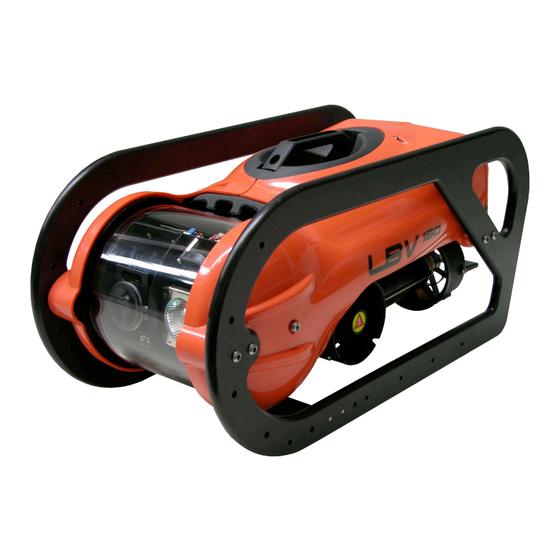
Purpose of this Procedures Manual The purpose of this procedures manual is to provide LBV operators with necessary information to repair LBV. If any part of the procedures is unclear contact SeaBotix Inc. or an authorized distributor for more detailed information. - Page 3 Protective Shell & Bumper Frame Introduction is fitted with a Protective Shell and Bumper Frame. The purpose of the protective shell is to protect the internal components as well as provide a more hydrodynamic shape through the water. In addition, the LBV systems are fitted with a protective bumper frame offering further protection, mounting for the ballast weight and various optional accessories.
- Page 4 Removal Step 1 Place the LBV on its starboard side. Step 2 – Phillips #2 Screwdriver Remove the 2 M5 x 12 Button head socket screws securing the crossbar to the starboard bumper frame rail. Note: there is a washer with each screw. Step 3 –...
- Page 5 Step 6 Lift off the port shell and bumper frame assembly. Note: be careful not to scratch the view port with the crossbar. Step 7 Turn the LBV over and place on its port side. Step 8 – 10mm Socket Head Driver Repeating a similar process to the port shell remove the 10mm hex nut at the front of the starboard shell.
-
Page 6: Installation
Step 11 Lift off the shell and bumper frame assembly then place LBV on its back. Removal process complete. Installation Step 1 Place the LBV on its port side with the accessory ports up. Step 2 Take the protective shell and bumper frame assembly and lower onto the LBV. - Page 7 Step 5 – Phillips #2 Screwdriver Insert the M4 x 50 Phillips pan head screw into the rear of the shell. Guide the screw through the gray plastic spacer and tighten into the float insert. Step 6 Turn the LBV over onto its starboard side. Step 7 Lower the port shell and bumper frame assembly onto the LBV aligning the forward threaded stud and lip under the shell to...
- Page 8 Step 10 – Phillips #2 Screwdriver Insert and tighten the M4 x 10 Phillips pan head screw into the rear of the shell. Step 11 – Phillips #2 Screwdriver Insert and tighten the 2 M5 x 12 button head screws securing the crossbar to the port bumper frame rail.
- Page 9 Flotation Module Introduction Providing buoyancy for the LBV is the flotation module. The flotation module is located behind the protective shell. Mounting points for the shell are located on the flotation module as well as the front camera housing. The flotation module mounts directly to the back plane. Work Environment Prior to beginning ensure you have a clean and dry workspace.
- Page 10 Removal Prior to performing this procedure you must first follow these procedures: • Shell/Bumper frame removal Step 1 Place the LBV upside down. Step 2 – Phillips #2 Screwdriver Remove the 2 M4x6 Phillips pan head screws securing the rear trim tab to the thruster Kort nozzles.
- Page 11 Step 5 – Phillips #2 Screwdriver Remove the 2 M4x10 Phillips pan head screws located in the middle of the flotation module near the vertical thruster elbow. Step 6 – 4mm Hex Ball Driver Remove the 2 M6x16 button head cap screws at the front of the float securing the camera housing end caps and flotation module.
- Page 12 Step 3 – Phillips #2 Screwdriver Insert and tighten the M6x16 button head cap screws into the forward part of the flotation module. Note: make sure the nylon washers are on the screws prior to installing. Step 4 – Phillips #2 Screwdriver Insert and tighten the 2 M4x10 Phillips pan head screws located at the rear of the float.
- Page 13 Once complete follow the procedures to: • Install Shell/Bumper Frame...
- Page 14 Vertical Thruster Introduction The LBV is fitted with four (4) identical thrusters. They can be interchanged to any position. Each thruster is isolated from the main housing and other thrusters. They have a four (4) pin connector for power and data. There is an o-ring seal around the connector. Work Environment Prior to beginning ensure you have a clean and dry workspace.
- Page 15 Removal Prior to performing this procedure you must first follow these procedures: • Flotation module removal • Shell/Bumper frame removal Step 1 Place LBV upside down. Step 2 - #2 Phillips Screwdriver Remove the 2 Phillips pan head screws securing the vertical thruster to the thruster elbow.
- Page 16 Step 5 Be sure to remove o-ring from elbow if stuck to surface. Installation Step 1 – O-ring Lube Lubricate the o-ring and place in groove on thruster connector. Step 2 Slide thruster up through hole in back plane and align 4 pins. Step 3 Push thruster straight onto pins.
- Page 17 Step 4 - #2 Phillips Screwdriver Insert and tighten the 2 Phillips pan head screws securing the thruster to the elbow. Note: be careful not to over tighten and strip threads. Once complete follow the procedures to: • Install flotation module •...
- Page 18 Lateral Thruster Introduction The LBV is fitted with four (4) identical thrusters. They can be interchanged to any position. Each thruster is isolated from the main housing and other thrusters. They have a four (4) pin connector for power and data. There is an o-ring seal around the connector. Work Environment Prior to beginning ensure you have a clean and dry workspace.
- Page 19 Removal Prior to performing this procedure you must first follow these procedures: • Flotation module removal • Shell/Bumper frame removal Step 1 Place LBV on its side. Step 2 - #2 Phillips Screwdriver Remove the 3 Phillips pan head screws securing the lateral thruster to the back plane.
- Page 20 Installation Step 1 – O-ring Lube Lubricate the o-ring and place in groove on thruster connector. Step 2 Push the lateral thruster onto the 4 pins. Note: make sure you push on straight so as not to damage the pins. Step 3 - #2 Phillips Screwdriver Insert and tighten the forward Phillips pan head screw.
- Page 21 Once complete follow the procedures to: • Install flotation module • Install Shell/Bumper Frame...
- Page 22 Port Forward Thruster Introduction The LBV is fitted with four (4) identical thrusters. They can be interchanged to any position. Each thruster is isolated from the main housing and other thrusters. They have a four (4) pin connector for power and data. There is an o-ring seal around the connector. Work Environment Prior to beginning ensure you have a clean and dry workspace.
- Page 23 Removal Prior to performing this procedure you must first follow these procedures: • Flotation module removal • Shell/Bumper frame removal Step 1 Place LBV upside down. Step 2 - #2 Phillips Screwdriver Remove the 3 Phillips pan head screws holding the port thruster Kort nozzle in place and remove Kort nozzle.
- Page 24 Step 5 Holding the power can with your fingers and using your thumb to leverage against the back plane carefully pry open the power can. Note: you will release the vacuum so do this process slowly and ensure there is no water that will enter the power can. Step 6 The o-ring will slip into the power can so locate the o-ring and wrap around the power can tube.
- Page 25 Step 10 Check to see if the o-ring has stuck to the back plane and remove if it has. Installation Step 1 – O-ring Lube Lubricate the o-ring and place in groove on the thruster connector. Step 2 Push the port thruster onto the 4 pins. Note: make sure you push on straight so as not to damage the pins.
- Page 26 Step 4 - #2 Phillips Screwdriver Insert and tighten the 2 Phillips pan head screws on the thruster connector at the rear of the thruster. Step 5 Making sure not to pinch any wires push the power can tube into the groove on the starboard power can end cap.
- Page 27 Step 9 – O-ring Insertion Tool Repeat this process pushing the o-ring into place for a full 90º around the power can. Tip: push straight down so you don’t stretch the o-ring. If excess occurs stop and start over. Step 10 – O-ring Insertion Tool Repeat the process on the opposite side for 90º...
- Page 28 Step 14 Place the LBV upside down. Step 15 - # Phillips Screwdriver Push on the Kort nozzle and insert and tighten the 3 Phillips pan head screws. Note: do not over tighten and strip out the threads. Once complete follow the procedures to: •...
- Page 29 Starboard Forward Thruster Introduction The LBV is fitted with four (4) identical thrusters. They can be interchanged to any position. Each thruster is isolated from the main housing and other thrusters. They have a four (4) pin connector for power and data. There is an o-ring seal around the connector. Work Environment Prior to beginning ensure you have a clean and dry workspace.
- Page 30 Removal Prior to performing this procedure you must first follow these procedures: • Flotation module removal • Shell/Bumper frame removal Step 1 Place LBV upside down. Step 2 - #2 Phillips Screwdriver Remove the 3 Phillips pan head screws holding the port thruster Kort nozzle in place and remove Kort nozzle.
- Page 31 Step 5 Holding the power can with your fingers and using your thumb to leverage against the back plane carefully pry open the power can. Note: you will release the vacuum so do this process slowly and ensure there is no water that will enter the power can. Step 6 The o-ring will slip into the power can so locate the o-ring and wrap around the power can tube.
- Page 32 Step 10 Check to see if the o-ring has stuck to the back plane and remove if it has. Installation Step 1 – O-ring Lube Lubricate the o-ring and place in groove on the thruster connector. Step 2 Push the starboard thruster onto the 4 pins. Note: make sure you push on straight so as not to damage the pins.
- Page 33 Step 4 - #2 Phillips Screwdriver Insert and tighten the 2 Phillips pan head screws on the thruster connector at the rear of the thruster. Step 5 Making sure not to pinch any wires push the power can tube into the groove on the starboard power can end cap.
- Page 34 Step 9 – O-ring Insertion Tool Repeat this process pushing the o-ring into place for a full 90º around the power can. Tip: push straight down so you don’t stretch the o-ring. If excess occurs stop and start over. Step 10 – O-ring Insertion Tool Repeat the process on the opposite side for 90º...
- Page 35 Step 14 Place the LBV upside down. Step 15 - #2 Phillips Screwdriver Push on the Kort nozzle and insert and tighten the 3 Phillips pan head screws. Note: do not over tighten and strip out the threads. Once complete follow the procedures to: •...
-
Page 36: View Port
View Port Introduction The LBV has a main front housing for the electronics, cameras and internal lighting. An acrylic cylinder is used as the view port. The acrylic works well in water even if scratched as it has the same refractive index as water. Also the view port can be rotated to clear up heavily scratched areas. - Page 37 Removal Step 1 Place LBV on the starboard side. Step 2 – 3mm Hex Ball Driver Remove the 2 M5x12 button head screws securing the center crossbar to the starboard bumper frame rail. Step 3 – 10mm Socket Remove the M6 nut at the front of the port shell. Step 4 - #2 Phillips Screwdriver Remove the M4x10 Phillips pan head screw at the rear of the port shell.
- Page 38 Step 6 Remove the port shell and bumper frame assembly. Step 7 - #2 Phillips Screwdriver Remove the 3 Phillips screws holding the lateral Kort nozzle in place and remove the Kort nozzle. Step 8 – 4mm Hex Ball Driver Loosen but do not remove the M6x16 button head screw securing the port camera housing end cap to the back plane and float.
- Page 39 Step 11 – View Port Sleeve Slide the view port protective sheet between the view port and camera chassis. Step 12 Holding the view port with your fingers and putting your thumbs on the center support rod pull up with your fingers and remove the view port.
- Page 40 Step 3 – View Port Sleeve With the protective sleeve in place slide the view port down onto the starboard camera housing end cap at an angle. Step 4 Push down from one angle to the other and feel the view port click into place.
- Page 41 Step 8 – 11/16 Socket Apply grease to the jacking plug o-ring and insert and tighten into the port camera housing end cap. Make sure the clamp bracket is resting against the back plane. Step 9 – 4mm Hex Ball Driver Tighten the M6x16 button head screw securing the port camera housing end cap to the back plane and flotation module.
- Page 42 Step 13 - #2 Phillips Screwdriver Insert and tighten the rear M4x10 Phillips pan head screw securing the rear of the port shell to the flotation module. Step 14 - #2 Phillips Screwdriver Insert and tighten the 2 M4x20 Phillips pan head screws into the middle upper portion of the port shell.
-
Page 43: Vacuum Check
21. Vacuum Check Introduction The LBV is fitted with a vacuum check valve. This valve is used to check the integrity of the seals on the main housing and power can when opened or transported commercially. The quick process provides peace of mind against potential leaking. Work Environment Prior to beginning ensure you have a clean and dry workspace. - Page 44 Step 1 Place LBV on table with vacuum port facing you. Step 2 - #2 Phillips Screwdriver Remove Phillips pan head seal screw from vacuum valve. Step 3 Connect vacuum hose and ensure fitting is tight. Step 4 – Vacuum Pump Connect vacuum pump to hose.
- Page 45 Step 6 Remove vacuum tube. Step 7 - #2 Phillips Screwdriver Insert and tighten Phillips pan head screw into check valve.
- Page 46 Lamp Introduction The LBV is fitted with an internal halogen lamp that tracks with the primary color camera. Life expectancy of the lamp is thousands of hours, however, they may on occasion be damaged in transit. Work Environment Prior to beginning ensure you have a clean and dry workspace. Locate the required tools and parts and have paper towels available.
- Page 47 Removal Prior to performing this procedure you must first follow these procedures: • Remove view port – NOTE that the view port itself does not have to be removed. Step 1 Gain access to camera housing. Step 2 Remove drive belt from tilt motor and pulley. Step 3 –...
- Page 48 Step 5 Push lever releasing lamp. Step 6 Remove lamp. Installation Step 1 Push new lamp into place being careful to align pins. Step 2 Locate tilt pulley and align groove with camera angle stop screw on camera chassis. Step 3 Stop screw on camera chassis.
- Page 49 Step 4 Tilt camera chassis so primary camera is facing straight down. Rotate pulley clockwise to stop. This sets the field of vision for the camera chassis. Step 5 – 1.5mm Hex Ball Driver Tighten set screws evenly. Be careful not to over tighten. Step 6 Wrap drive belt around tilt motor pulley one and one half times (double wrap, not figure eight).
- Page 50 Once complete follow the procedures to: • Install view port...
- Page 51 Motherboard Introduction The LBV has a primary control board called the motherboard. Other small daughter boards are connected to it such as the RF Modulator and the Video Overlay. The motherboard is the main interface board. Work Environment Prior to beginning ensure you have a clean and dry workspace. Locate the required tools and parts and have paper towels available.
- Page 52 Removal Prior to performing this procedure you must first follow these procedures: • View port removal • RF modulator removal • Video overlay removal Step 1 Place LBV with electronics facing you. Step 2 Carefully unplug power connector, and two small green JST connectors from motherboard.
- Page 53 Step 5 – Small Straight Blade Screwdriver Remove 4 white nylon screws securing motherboard and 6 standoffs. Step 6 Unplug light from motherboard. Step 7 Carefully remove motherboard. Installation Step 1 Carefully fit new motherboard. Feed motor and camera wires into cut out on motherboard in this order and connect.
- Page 54 Step 2 – Small Straight Blade Screwdriver Insert and tighten 4 nylon screws and 6 standoffs. Careful not to over tighten nylon screws and pinch any wires. Step 3 Connect light to outside connector for camera one. Step 4 Reconnect power connector and two small green JST connectors.
- Page 55 RF Modulator Introduction Mounted on the motherboard is the RF modulator. This board is responsible for the data communications as well as the video transmission. Care must be taken with the connectors. Work Environment Prior to beginning ensure you have a clean and dry workspace. Locate the required tools and parts and have paper towels available.
- Page 56 Removal Prior to performing this procedure you must first follow these procedures: • View port removal Step 1 Place vehicle upside down. Step 2 Rotate camera chassis until electronics are visible. Step 3 With your thumb hold down surface mounted coaxial connector and with other hand pry up cable connectors.
- Page 57 Step 5 - #1 Phillips Screwdriver Remove 3 M3x6 Phillips pan head screws securing RF Modulator board to motherboard. Step 6 Remove RF modulator board. Installation Step 1 Locate new RF modulator board. Step 2 Carefully lower new RF board onto pins aligning mounting holes.
- Page 58 Step 4 Carefully push coaxial connectors onto coaxial connectors on RF modulator board. Green is data (center of camera chassis) Red is video (outside of camera chassis) Once complete follow the procedures to: • Install view port...
-
Page 59: Video Overlay
Video Overlay Introduction Mounted on top of the motherboard is a small electronics board. The video overlay board is responsible for generating the on screen information. Work Environment Prior to beginning ensure you have a clean and dry workspace. Locate the required tools and parts and have paper towels available. - Page 60 Removal Prior to performing this procedure you must first follow these procedures: • View port removal Step 1 Place vehicle upside down. Step 2 Rotate camera chassis until electronics are visible. Step 3 Unplug wire to fan from overlay board. Step 4 - #1 Phillips Screwdriver Remove 3 M3x6 Phillips pan head screws securing Video Overlay board to motherboard.
- Page 61 Step 5 Carefully remove overlay board. Installation Step 1 Locate new overlay board. Step 2 Carefully lower new Video Overlay board onto motherboard aligning pins correctly. Failure to align correctly can damage Video Overlay and/or motherboard. Step 3 - #1 Phillips Screwdriver Insert and tighten 3 x M4 Phillips pan head screws securing overlay board to motherboard.
- Page 62 Once complete follow the procedures to: • Install view port...
-
Page 63: Sensor Board
Sensor Board Introduction The LBV has a round electronics board mounted in the starboard camera housing end cap. This board called the Sensor board interfaces between the depth, temperature and heading sensors and the motherboard. It also acts as a connection point for some options. Work Environment Prior to beginning ensure you have a clean and dry workspace. - Page 64 Removal Prior to performing this procedure you must first follow these procedures: • View port removal Step 1 Lift camera chassis from center rod and set to one side. Step 2 Remove camera chassis spacer from center rod. Step 3 - #1 Phillips Screwdriver Remove 4 x Phillips pan head screws securing sensor board to camera housing end cap.
- Page 65 Step 5 Raise sensor board and unplug both connectors. Step 6 Remove sensor board and set aside. Installation Step 1 Lower sensor board onto center rod. Connect both connectors and align heading sensor with front cutout. Step 2 Lower sensor board and single white nylon spacer being sure to align holes.
- Page 66 Step 4 - #1 Phillips Screwdriver Insert and tighten 4 x Phillips pan head screws. Careful not to over tighten as service loop protector will crack. Step 5 Lower service loop spacer onto center rod. Step 6 Wrap service loop around center rod and lower camera chassis onto rod.
- Page 67 Heading Sensor Board Introduction The LBV is fitted with a magnetic compass mounted to a small board. This heading board is mounted to the sensor board inside the starboard camera housing end cap. Work Environment Prior to beginning ensure you have a clean and dry workspace. Locate the required tools and parts and have paper towels available.
- Page 68 Prior to performing this procedure you must first follow these procedures: • View port removal • Sensor board removal Step 1 Unplug heading sensor from sensor board. Step 2 Locate new heading sensor. Step 3 Plug new heading sensor onto sensor board being careful to align pins correctly.
-
Page 69: Depth Sensor
Depth Sensor Introduction The LBV has an external depth and temperature sensor installed in the starboard camera housing end cap. Housed in an aluminum casing and potted. The depth sensor communicates with the sensor board. Work Environment Prior to beginning ensure you have a clean and dry workspace. Locate the required tools and parts and have paper towels available. - Page 70 Prior to performing this procedure you must first follow these procedures: • View port removal • Sensor board removal Step 1 Place vehicle upside down. Step 2 – 19mm Open End Wrench Loosen depth sensor from camera housing end cap. Step 3 Remove depth sensor from camera housing end cap.
- Page 71 Step 5 Carefully push connector through camera housing end cap. Step 6 – 19mm Open End Wrench Tighten depth sensor into camera housing end cap. Once complete follow the procedures to: • Install view port • Install sensor board...
-
Page 72: Vehicle Power Supply
Vehicle Power Supply Introduction Inside the power can is the vehicle power supply, which is responsible for the power management and interface for the LBV Work Environment Prior to beginning ensure you have a clean and dry workspace. Locate the required tools and parts and have paper towels available. - Page 73 Removal Prior to performing this procedure you must first follow these procedures: • Shell/Bumper frame removal • Flotation module removal Step 1 Make sure all power is off and the umbilical is disconnected from the LBV vehicle. Step 2 Place LBV on starboard side. Step 3 - #2 Phillips Screwdriver Remove 3 Phillips pan head screws securing Kort nozzle to port thruster and remove Kort nozzle.
- Page 74 Step 5 – 3mm Hex Ball Driver Remove 2 M4x10 socket head button screws securing port power can end cap to back plane. Step 6 Using your thumb as leverage pry the power can apart at the starboard end cap being careful not to allow water to be pulled in when vacuum is released.
- Page 75 Step 10 Locate starboard power can sealing o-ring and slide over power can tube. Step 11 Compress aluminium plate on springs. Step 12 Slide power can off vehicle power supply being careful not to pull on wires. Step 13 Completely remove power can tube and place vehicle power supply on paper towel on back plane.
- Page 76 Step 15 - #2 Phillips Screwdriver Remove 2 M3x6 Phillips pan head screws securing video and data clamps to aluminium plate. Step 16 Remove clamps from video and data wires. Step 17 Carefully pry connectors free and separate cables from RF Coupler board.
- Page 77 Step 20 Locate 3 JST connectors on side of vehicle interface board. Step 21 – Small Straight Blade Screwdriver Using a small straight blade screwdriver carefully pry the JST connectors out of their sockets. Step 22 Separate all three connectors. Step 23 Guiding wires free of vehicle power supply it can be removed.
- Page 78 Step 2 Feed green JST connectors through vehicle power supply to receptacles. Step 3 Carefully press each of the 3 connectors into their respective receptacle. There is an alignment pin to ensure correct location as well as each connector has a different number of pins.
- Page 79 Step 7 – Small Straight Blade Screwdriver Insert black lead from motherboard into last connector marked GRND and tighten with small straight blade screwdriver. Step 8 Carefully press video (red) and data (green) connectors onto RF coupler board following the printing on the board. Step 9 - #2 Phillips Screwdriver Insert and tighten 2 x M3x6 Phillips pan head screws securing clamps to RF coupler board.
- Page 80 Step 12 – Small Straight Blade Screwdriver Insert wire marked 2 into connector slot 2 on top of RF coupler board. Step 13 – Small Straight Blade Screwdriver Insert wire marked 3 into connector slot 3 on top of RF coupler board.
- Page 81 Step 17 – O-ring Grease Apply silicone grease to power can o-rings. Step 18 Slide o-rings over power can tube. Step 19 Place LBV on starboard side. Step 20 Being careful not to pinch wires push power can tube into groove in starboard end cap.
- Page 82 Step 22 Insert second M5x10 socket head button screw securing port power can end cap to back plane. Step 23 – 3mm Hex Ball Driver Tighten 2 M5x10 socket head button screws securing port power can end cap to back plane. Step 24 Push o-ring down to starboard power can end cap.
- Page 83 Step 27 – O-ring Insertion Tool Switch sides and work o-ring into groove. Step 28 – O-ring Insertion Tool Continue around power can tube pressing o-ring into place. Step 29 – O-ring Insertion Tool Switch sides and work o-ring into groove. Step 30 –...
- Page 84 Step 32 Turn LBV over onto port side Step 33 Push o-ring down to port power can end cap. Step 34 – O-ring Insertion Tool Starting from the back press the o-ring between power can tube and port power can end cap. Step 35 –...
- Page 85 Step 37 – O-ring Insertion Tool Switch sides and work o-ring into groove. Step 38 – O-ring Insertion Tool Once o-ring is completely pressed in smooth out any lumps. Step 39 Place LBV upside down. Step 40 Push Kort nozzle onto port thruster. Step 41 - #2 Phillps Screwdriver Insert and tighten 3 Phillips pan head screws securing Kort nozzle to port thruster.
- Page 86 Camera Introduction The LBV is fitted with one or two cameras in the front housing. Primary camera is color and the secondary camera is black and white. The small camera modules are mounted in a special bracket in turn mounted to the camera chassis. They are connected to the motherboard.
- Page 87 Removal Prior to performing this procedure you must first follow these procedures: • View port removal • RF modulator removal • Video Overlay removal • Motherboard removal Step 1 - O-ring Insertion Tool Remove 2 M2.5x4 Phillips pan head screws securing camera to camera chassis.
- Page 88 110/220 VAC Change Introduction The LBV is capable of accepting input power ranging from 100-130VAC and 200-240VAC. A simple connector is moved to enable the varying input power. Work Environment Prior to beginning ensure you have a clean and dry workspace. Locate the required tools and parts and have paper towels available.
- Page 89 Step 1 Disconnect all cables from surface power supply. Step 2 Place surface power supply on non-connector heat sink. Step 3 – 2.5mm Hex Ball DRiver Remove 12 x M4X20 socket head cap screws securing heat sink to surface power supply box. Step 4 Carefully lift heat sink exposing connectors.
- Page 90 Step 6 Lower heat sink back onto surface power supply box being careful not to catch any wires. Step 7 – 2.5mm Hex Ball Driver Insert and tighten all 12 x M6X20 socket head cap screws securing heat sink to surface power supply box.
- Page 91 The LBV programmer requires a PC compatible computer with either Windows 2000, XP or NT operating system. Performance specifications are only basic. Software for the update and the LBV programmer can be located on the SeaBotix website under Support and Software Downloads.
- Page 92 Step 1 Setup entire LBV system with monitor. Step 2 Copy down current software prior to loading new software. Refer to users manual. Step 3 Connect RS232 cable to surface power supply. Step 4 Open LBV Programmer on PC. Do NOT use Windows 3.x, 95 or 98 as they will erase on not program your LBV.
- Page 93 Step 6 Select desired version of software. Make sure you are selecting the right software for the right motherboard. Step 7 Click Program. Step 8 Power On LBV. Step 9 Auto heading and depth LEDs will flash rapidly and there will be no picture on the monitor.
- Page 94 Step 11 Once programming is complete picture will come up and status will be finished on the computer.
- Page 95 Control Console Processor Introduction In addition to the LBV software is the control console software. This software is programmed into the microchip located on the control console electronics board. It requires replacement when new software for the controller is developed. Work Environment Prior to beginning ensure you have a clean and dry workspace.
- Page 96 Step 1 - #1 Phillips Screwdriver Place control console upside down and remove 4 x Phillips pan counter sunk screws securing bottom of control console to top. Step 2 Slide rear cover off and to side. Step 3 – Processor Removal Tool Insert 2 prongs into either side of microprocessor and gently squeeze and pull to remove micro processor.
- Page 97 Step 6 - #1 Phillips Screwdriver Insert and tighten 4 x Phillips counter sunk screws securing back cover to top.
- Page 98 Thruster Grease Overhaul Introduction The LBV is fitted with four identical thrusters. Protecting the shaft seal and shaft is a grease gallery. After approximately 50 hours of use it is recommended that the grease be refreshed. The process is very simple and the special grease is supplied. Work Environment Prior to beginning ensure you have a clean and dry workspace.
- Page 99 Prior to performing this procedure you must first follow these procedures: • Shell/Bumper frame removal • Flotation module removal Step 1 Place vehicle upside down. Step 2 - #2 Phillips Screwdriver Remove the six (6) Phillips head screws securing the forward Kort nozzles to the forward thruster assemblies and remove Kort nozzles.
- Page 100 Step 5 Push grease into the gallery until the expelled grease at the opposite end of the propeller end cap is clean grease. Step 6 Repeat steps 11 and 12 for each thruster. Step 7 - #2 Phillips Screwdriver Reinstall the black plastic screws into each thruster propeller end cap being careful not to over tighten.
- Page 101 Once complete follow the procedures to: • Install flotation module • Install Shell/Bumper frame...
Need help?
Do you have a question about the Generation 2 and is the answer not in the manual?
Questions and answers