Table of Contents
Advertisement
Advertisement
Table of Contents

Related Manuals for HP XP-P4IM533GV


Summary of Contents for HP XP-P4IM533GV
- Page 1 XP-P4IM533GV ® ® Intel Pentium 4 Processor Motherboard User's Manual M-040402...
- Page 2 If your system is not turned off during installation, this could result in harm or damage to the motherboard, the components as well as to the user. Motherboard XP-P4IM533GV Motherboard XP-P4IM533GV May 11, 2004...
-
Page 3: Table Of Contents
Contents Motherboard Layout ................4 Production Introduction ............... 5 1.1. Feature Summary ................5 1.2. I/O Back Panel and Connectors&Jumper Setting ......6 1.2.1. I/O Back Panel ..................6 1.2.2. Connectors&Jumper Setting ............... 6 Hardware Installation ..............9 2.1. Installation of a Pentium 4 CPU and Fan Sink ........ 9 2.2. -
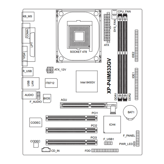
Page 4: Motherboard Layout
Motherboard Layout CPU_FAN KB_MS SOCKET 478 ATX_12V R_USB Intel 845GV IT8712 AUDIO BIOS F_AUDIO BAT1 PCI1 CODEC ICH4 PCI2 F_PANEL PCI3 F_USB1 CODEC PWR_LED CD_IN... -
Page 5: Production Introduction
Production Introduction The user manual provides steps related to quick installation. If you wish to view complete product information, please select the " ",Open User Manual button located on the driver CD or link to our website at http://www.axper.com to received the most up-to-date information. 1.1. -
Page 6: I/O Back Panel And Connectors&Jumper Setting
1.2. I/O Back Panel and Connectors&Jumper Setting 1.2.1. I/O Back Panel Parallel Port PS/2 Mouse Line In Line Out MIC In PS/2 Keyboard COM A PS/2 Keyboard Connects PS/2 standard keyboard and PS/2 standard PS/2 Mouse connector mouse Prior to use, please make sure that your system as well (Universal Serial Bus Port) as the connected attachments support the USB interface. - Page 7 CPU_FAN (CPU Fan Power Connector); SYS_FAN (System Fan Power Connector) The cooler fan power connector supplies a +12V power voltage via a 3-pin power connector and possesses a ful-proof connection design. Most coolers are designed with color-coded power connector wires. A red power connector wire indi- cates a positive connection and requires a +12V power voltage.
- Page 8 PWR_LED Connects to the system power LED indicator whereby the power is indicated as ON or OFF. However, the indicator will flash when the system is suspended. SIGNAL MPD+ MPD- MPD- F_AUDIO (Front Audio Connector) Connects to the audio connector located on the front panel of the system casing (dependent on case design).
-
Page 9: Hardware Installation
BAT1(Battery) The improper removal of the battery can result in harm. When replacing a battery, please make sure you use one that is of similar brand and model number. For information related to battery specifications and precautions, please refer to the manufacturer instructions. If you wish to delete the data stored in the CMOS, please follow the steps below: 1. -
Page 10: Installation Of Memory
When the CPU is inserted into its position, gently press the metal lever downwards until a click is heard. Then add an even layer of heat sink paste between the CPU and fan sink for heat dissipation. Position and attach the clips on one end of the fan sink firmly atop the CPU. -
Page 11: Installation Of The Graphics Card
2.3. Installation of the Graphics Card 1. Before installing the graphics card, please carefully read the accompanying user manual. As well, make sure the computer power is turned off. 2. When installing or removing the graphics card, first pull out the white AGU knob before insertion or removal. - Page 12 Figure 1-2. 4X AGP Card Graphics Chip Maker Model Name Nvidia Gigabyte GA-GF2000 Gigabyte GA-GF1280 Gigabyte GV-GF2010D Gigabyte GA-GF3000D Gigabyte GV-GF1280-32E Gigabyte GV-GF1280T-32P Gigabyte GV-GF3200TF Gigabyte GV-GF3500TF-GH ELSA Gladiac Ultra ELSA Gladiac 517 ELSA Gladiac 517vivo ELSA Gladiac 525 A128 Leadtek WinFast A170 TH Leadtek...
-
Page 13: Bios Setup
BIOS Setup BIOS (Basic Input and Output System) stores all the information of the motherboard settings that is needed for system initiation within the CMOS. The CMOS SETUP utility allows the user to make changes in BIOS configurations that are required or to activate certain features. The CMOS SETUP saves each item configuration in the CMOS SRAM of the motherboard. -
Page 14: Standard Cmos Features
<F6> Gives the list of options available for each item <F7> Return to Optimized default values (not applicable to main setup screen) <F8> Enters Expert-Flash feature <F9> Displays system information <F10> Saves settings and exits setup 3.2. Standard CMOS Features ø... - Page 15 n n n n n Floppy 3 Mode Support Allows user to configure a Japanese standard 3 Mode floppy drive. Options: Disabled (No 3 Mode drive installed) Drive A (3 Mode Drive installed in A:) Drive B (3 Mode Drive installed in B:) Both (3 Mode Drive installed in A: and B:) n n n n n Halt on Tells the BIOS specifically which types of errors will halt the computer during the power-...
-
Page 16: Advanced Bios Features
3.3. Advanced BIOS Features ø Allows the configuration of advanced settings such as boot sequence, password check, etc. CMOS Setup Utility-Copyright (C) 1984-2004 Award Software Advanced BIOS Features First Boot Device [Floppy] Item Help Second Boot Device [HDD-0] Menu Level} Third Boot Device [CDROM] Select Boot Device... -
Page 17: Integrated Peripherals
n n n n n Graphics Memory Size Allows user to set the size of the graphics memory for improved memory performance. Options: 128MB/Disabled (default:128MB) n n n n n Graphics Share Memory Allows user to set the amount of memory given for the graphics card frame buffer. Options: 8MB/1MB (default:8MB) 3.4. - Page 18 n n n n n USB Controller Allows the user to enable or disable the onboard USB2.0 controller. (default:Enabled) n n n n n USB Keyboard Support Allows user to use a USB-based keyboard (Enable if you are using a USB keyboard, otherwise Disable) (default:Disabled) n n n n n USB Mouse Support Allows user to use a USB-based mouse (Enable if you are using a USB mouse,...
-
Page 19: Power Management Setup
3.5. Power Management Setup ø This is used to control the various power saving features of the PC. CMOS Setup Utility-Copyright (C) 1984-2004 Award Software Power Management Setup ACPI Suspend Type [S1(POS)] Item Help Soft-Off by PWR-BTTN [Instant-Off] Menu Level} PME Event Wake Up [Enabled] [S1]... -
Page 20: Pnp/Pci Configuration
n n n n n KB Power ON Password Allows user to set a 1-5 character long password for powering on the keyboard. Select Enter to complete setting. n n n n n AC Back Function Allows user to select system status when power is removed and returned. Options: Memory (return prior to power removal) Full-On (return to full system power) -
Page 21: Pc Health Status
3.7. PC Health Status ø This menu displays the current CPU temperature, the fan speeds, voltages etc. CMOS Setup Utility-Copyright (C) 1984-2004 Award Software PC Health Status Vcore 1.54V Item Help DDR25V 2.544V Menu Level} +3.3V 3.360V +12V 11.92V Current CPU Temperature 45°C Current CPU FAN Speed 4440 RPM... -
Page 22: Frequency/Voltage Control
3.8. Frequency/Voltage Control ø This allows user to configure CPU frequency and voltage settings. CMOS Setup Utility-Copyright (C) 1984-2004 Award Software Frequency/Voltage Control CPU Clock Ratio [15X] Item Help CPU Host Clock Control [Disabled] Menu Level} ø CPU Host Frequency (Mhz) Set CPU Ratio if CPU Host/DRAM Clock ratio [Auto]... - Page 23 n n n n n Host/DRAM Clock Ratio Allows the user to set the Host/DRAM Clock Ratio. If the FSB(Front Side Bus) is at 400MHz. 2.66 Memory Frequency = Host clock x 2.66. Auto Automatically sets memory frequency. (default:Auto) If the FSB(Front Side Bus) is at 533MHz. Memory Frequency = Host clock x 2.0.
-
Page 24: Top Performance
3.9. Top Performance ø "Top Performance" allows faster system start. However, the result may differ depending on system specifications (includes hardware and OS). For example, certain hardware may become unstable under Windows XP but work reliably under the Windows NT operating system. -
Page 25: Driver Installation
Driver Installation Driver installation for the Windows 98/98SE/200/ME/XP operating systems is simple. Once you insert the provided driver disks into your optical drive, the AUTORUN screen will appear. If this screen does not appear, you can use "D:\setup.exe" (with "D" being the specified drive) to bring up the screen shown below.
Need help?
Do you have a question about the XP-P4IM533GV and is the answer not in the manual?
Questions and answers