Table of Contents
Advertisement
Advertisement
Table of Contents

Related Manuals for Danfysik SYSTEM 9100

Summary of Contents for Danfysik SYSTEM 9100
- Page 1 MANUAL MAGNET POWER SUPPLY SYSTEM 9100...
- Page 2 REV. Date Description Pages 12.04.2010 Initial Chapter 2.5: Two or more SYSTEM 9100 in 18.06.2010 parallel deleted Chapter 5: AC mains Connector X1. 208VAC pin 19.08.2010 connections added 05.05.2011 Various ESHA 19.12.2012 Address IMPORTANT! This documentation contains information which is the property of DANFYSIK A/S, Denmark.
-
Page 3: Table Of Contents
MAGNET POWER SUPPLY SYSTEM 9100 Table of contents PAGE INTRODUCTION AND SPECIFICATIONS ..................5 ....................... 5 ENERAL INTRODUCTION ..........................6 PECIFICATIONS ..................... 9 ARRANTY AND WARRANTY REPAIR UNPACKING AND INSTALLATION....................10 ......................... 10 ECEIVING THE GOODS ....................10 NSTRUCTIONS FOR UNPACKING ..................... - Page 4 (H-B ) ................... 57 IPOLAR OUTPUT STAGE RIGDE SYSTEM 9100 INTERFACE SPECIFICATION: ................58 AC Mains connector X1: ........................58 Output X24 and X25 ..........................58 Analog X108 (D-SUB 25 Pole): ......................59 SPI – Iset DAC interface X5 (HDMI 19- Pole): .................. 59 LOCAL CONTROL X6 (D-SUB 9 Pole): ...................
-
Page 5: Introduction And Specifications
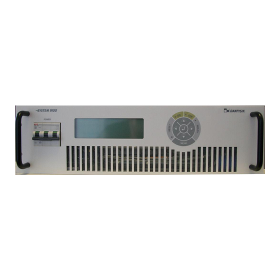
The System 9100 is aimed at correction magnets in ion beam applications based on Danfysik´s forty years of experience in delivering precision DC Power supplies to industrial and research laboratory users around the world. -
Page 6: Specifications
MAGNET POWER SUPPLY SYSTEM 9100 Specifications AC INPUT Mains, voltage: 400 VAC, 3 phase, 47 - 63 Hz. Control voltage: 230 VAC, 47-63 Hz. AC voltage variation: ±10% See page 58 for connection to AC mains connector. DC OUTPUT Power Range... - Page 7 MAGNET POWER SUPPLY SYSTEM 9100 Current readback resolution: 16 bit ADC Voltage readback resolution: 16 bit ADC 1 – 100% Current control range (setting range): Ramp speed (0 – 100%): 0.1 – 10 s (adjustable)* 2 – 100 Hz Current loop bandwidth: Voltage loop bandwidth: >200 Hz...
- Page 8 MAGNET POWER SUPPLY SYSTEM 9100 Interlock status Over voltage Over current Over temperature Fan fault Earth leakage AC fault Out of regulation External interlock (ext. 1 – 4) Summary interlock COOLING Water: 1 l/min @ max. Inlet temperature 35° C...
-
Page 9: Warranty And Warranty Repair
Repair work, which is warranted for six (6) months from the date of shipment from the DANFYSIK works. DANFYSIK A/S will repair or replace either on site or at the factory, at option and without charge, any equipment which proves to be defective within its warranty period. -
Page 10: Unpacking And Installation
The Power Supply is shipped in reinforced cardboard. If the equipment is damaged in any way, a claim should be filed with the shipping agent, and a full report of the damage should be forwarded to DANFYSIK A/S or our local agent/- representative immediately. -
Page 11: Installation
MAGNET POWER SUPPLY SYSTEM 9100 No other additives should be used. During operation, the conductivity of the coolant should be checked regularly. A few days operation with water of poor quality can cause more corrosion damage than during several years‟ operation with good quality water. -
Page 12: Rs422 Or Rs485 Multidrop Configuration
MAGNET POWER SUPPLY SYSTEM 9100 RS422 or RS485 Multidrop configuration Up to 32 SYSTEM 9100 units can be connected in a RS422 or RS485 multidrop configuration. It is also possible to run a Master/Slave configuration within a multidrop system. To set up the Master/Slave configuration, see chapter 2.5. -
Page 13: Operating Instructions
Danfysik Magnet Power Supplies including SYSTEM 9100. The SYSTEM 9100 comes with a M-panel as standard. It can however also be delivered with a display board. This has two 5 digit 7 segment displays for voltage and current. LED indicators for POWER ON, FAULT and READY. -
Page 14: Main Power On / Off And Interlock Reset
MAGNET POWER SUPPLY SYSTEM 9100 3.2.1 Main power ON / OFF and interlock RESET The basic function on the M-panel is to turn the power supply ON / OFF and to RESET pending interlocks. All controlled from a single button. For further information about the button locations, see chapter 3.2.3 Front Panel Control. - Page 15 MAGNET POWER SUPPLY SYSTEM 9100 As usual any rule has exceptions and these are: - If there is no need for parameters after activating the “ ” button “Stand alone menu” there is no need to press the “...
-
Page 16: Front Panel Controls
MAGNET POWER SUPPLY SYSTEM 9100 3.2.3 Front panel controls. 1. Graphic display 240*64 2. Main power is "ON" LED. 3. Main power "ON" push button. 4. Main power is "OFF" LED. 5. Main power "OFF" push button. 6. READY LED indicates when the... -
Page 17: The Display
"SET 000000 ppm". When full output current is set, it displays "Iset 999999 ppm", which is to be read as 99.9999 % of full scale. If required a setting in Ampere with six digits and a decimal point can be adapted. This will be set at Danfysik during test or by Danfysik service personnel. - Page 18 MAGNET POWER SUPPLY SYSTEM 9100 Bar Graph The bar graph is an analog representation of the actual output current. The output current is 100 % when the bar-graph is full. The minor tics are for 5% steps and the major tics for 10%.
- Page 19 MAGNET POWER SUPPLY SYSTEM 9100 Menu Window: Pressing the MENU button the Menu window will appear. The picture to the right shows the opening window if no interlock is present and after the “” button is pressed once. Editing Window: If a value needs editing a cursor, shown as an inverted character, will occur somewhere in the value.
-
Page 20: Control Menus
MAGNET POWER SUPPLY SYSTEM 9100 3.2.5 Control Menus The table below lists the standard menus. (Horizontal pop up layout) Scroll Sub menu 1 Sub menu 2 Sub menu 3 Comment menu Setting of output current CURRENT Set output current immediately... - Page 21 MAGNET POWER SUPPLY SYSTEM 9100 Scroll Sub menu 2 Sub menu 3 Comment menu LIMITS Value limitations Current value limitations Positive limit Negative limit AD-CHAN CHN 0-8 A/D Channels 0 to 8 Output current 3 significant digits Output current Hall-probe required.
-
Page 22: Current Setting
“” or “ ” button. Please be aware that the system 9100 power supply is designed to work mainly in the first and third quadrant, i.e. either positive output voltage and current or negative output voltage and current. Working in the second or fourth quadrant is limited to the safe operating area of the polarity switch transistors. - Page 23 MAGNET POWER SUPPLY SYSTEM 9100 DANFYSIK A/S - DENMARK.
-
Page 24: Operating By Rs 232, Rs422 Or Rs 485 I/O
MAGNET POWER SUPPLY SYSTEM 9100 Operating by RS 232, RS422 or RS 485 I/O The Control-Module uses standard serial interfaces compatible with many computers, PC and terminals. Two data communication lines are available: - A REMOTE LINE, with either RS232, RS422 or RS485 communication. - Page 25 MAGNET POWER SUPPLY SYSTEM 9100 Be aware when changing the Baud rates. Wrong setting may cause communication loss. Modifying a baud rate with the HW switches or through the appropriate SW command, will first take effect after a reset. At the remote line, use command ESC<CPURESET to make a reset.
- Page 26 MAGNET POWER SUPPLY SYSTEM 9100 UART HW SET UP (Esc<BAUD) In the “UART HW SETUP” mode the baud rate and associated parameters for the serial lines can be set. SW3 indicates witch line to set up. Hint: Selecting SW3 will immediately display the present setting on the red LEDs below SW4.
- Page 27 MAGNET POWER SUPPLY SYSTEM 9100 ADDRESS LINE SET UP (Esc<ADR) When using the RS422 or RS485 standard for the serial communication Remote or Local, it is possible to attach a specific address to the line for multi drop connection. The LOCAL line addressing can be used for controlling more power supplies through one Operator Control Panel.
- Page 28 MAGNET POWER SUPPLY SYSTEM 9100 LINE FUNCTION PROTOCOL SETUP (Esc<LINE) SW3 FOR LOCAL LINE SW3 FOR REMOTE LINE The “LINE FUNCTION PROTOCOL SETUP” is for setting up serial line protocols. Parameters: DISABLED ENABLED RS 485 COMMUNICATION DISABLED ENABLED RS 485 LINE TURN AROUND...
- Page 29 MAGNET POWER SUPPLY SYSTEM 9100 COLD BOOT SETUP (Esc<COLDBOOT) After power up or reset the power supply can wake up in different control conditions. The switch settings shown below describe the possible Wake up conditions. Parameters: SW3 FOR COLD BOOT INITIAL SETUP Default setting after “COLD BOOT”...
- Page 30 MAGNET POWER SUPPLY SYSTEM 9100 AUX SETUP (Esc<AUX) Special options can be initiated with the auxiliary switch set up 1. Setting of bit 16 and 17 is intended for Offset DAC use. That is a 16 bit setting between 88 and 96% (Bit16=0 &...
- Page 31 MAGNET POWER SUPPLY SYSTEM 9100 POLARITY DELAY TIME SETUP (Esc<POLDELAY) A time delay can be inserted between the OFF state and the activation of the polarity change over switch. The range of the time delay can be set from 0 to 25.5 seconds, (in steep of 100ms) this for letting the rest energy in the magnet to decay.
- Page 32 MAGNET POWER SUPPLY SYSTEM 9100 AD AUTO ADJUSTMENT (Gain & Offset) (Esc<ADSET) The scaling factors for the AD channels can automatically be adjusted with this setting. SW3 FOR ADSET Parameters CH_No. 2 CH_No. 2 CH_No. 2 CH_No. 2 CH_No. 2...
- Page 33 MAGNET POWER SUPPLY SYSTEM 9100 GAIN adjustment The GAIN adjustment can automatically adjust the scaling factor of the selected channel to only nines. That is e.g. 99999 for the 16 bit output current reading. This adjustment is only useful for the output current and voltage read back (CH0, CH2, CH8, CH11 and CH12) Please do not use this feature if the output reading is in Volts and Amps and for not applicable channels.
- Page 34 MAGNET POWER SUPPLY SYSTEM 9100 DA AUTO ADJUSTMENT (Gain & Offset) (Esc<DASET) The scaling factors for the DA channels can automatically be adjusted with this setting. This feature is specially designed for “non calibrated” SW3 FOR ADSET Parameters CH_No. 2 CH_No.
- Page 35 MAGNET POWER SUPPLY SYSTEM 9100 pressing the Setup Button. CHANNEL VALUE DA channel spec. Equal to 0 Output current 16 bit WA range as default 1 Not used 2 Not used 3 Not used 4 Output voltage 16 bit DANFYSIK A/S - DENMARK.
-
Page 36: Data Communication
3.3.2 Data communication The SYSTEM 9100 uses the standard serial interface RS 232 which is compatible with many computers and terminals. Beside RS232, SYSTEM 9100 supports RS422 and RS485. The connectors for the serial interface ports “REMOTE CONTROL” and “LOCAL CONTROL”... -
Page 37: Termination Using Rs 422M Or Rs 485
MAGNET POWER SUPPLY SYSTEM 9100 The default serial setting is: 8 BIT DATA, NO PARITY AND 1 STOPBIT and baud rate 115200. The communication is done by transmitting characters in ASCII code terminated by CARRIAGE RETURN. The termination characters from the Power Supply are CARRIAGE RETURN and LINE FEED. -
Page 38: Programming
Hint. When using the "Always Answer" mode a re-transmission of the last given command can be performed if no answer or an error message is received. The System 9100 respond time is around 5ms after receiving the last bit of the termination character. -
Page 39: Software Profile Programming
3.3.5 Software Profile Programming SYSTEM 9100 is delivered with the software ramp profile option. With the ramp profile SW it is possible to down load and run a predefined ramp sequence that the output current must follow. The ramp sequence can be programmed in two quite different methods. -
Page 40: Arbitrary Point Ramp Profile Method
MAGNET POWER SUPPLY SYSTEM 9100 3.3.6 Arbitrary point ramp profile method With the ”Arbitrary point method” it is possible to download up to fifteen independent points each generating a ramp line (through interpolation). This profile must be stored in one of the 15 available stacks. -
Page 41: Equal Time Slot Ramp Profile Method
MAGNET POWER SUPPLY SYSTEM 9100 If synchronization to an eternal event is required, it is possible to arm the ramp sequence first with the synchronization command “SYNC (stack no.), [trigger delay]”. A hardware signal on the trigger input X9 pin 1&2 (10 to 24V) or a TS command will start the sequence. If a trig delay is entered, the sequence will first start after the delay time has elapsed. -
Page 42: Auto Slew Rate Ramp Profile Method
MAGNET POWER SUPPLY SYSTEM 9100 The SW will after the start command update the output current every 1.25ms. By means of interpolation regardless of the programmed time slot value: The ramp can be set up to run as a single shot “RAMP R”, auto iteratively (auto loop) “RAMP RL”... -
Page 43: Sw Limits
MAGNET POWER SUPPLY SYSTEM 9100 The time slot must be given as a multiple of 1.25ms. Between 1.25ms to 1 second. Any value in-between will automatically be rounded according to formulae: {time slot}=frac({time}/0.00125)*0.00125 The ramp profile can be stopped either with a “STOP” command or when the power supply is turned OFF. - Page 44 MAGNET POWER SUPPLY SYSTEM 9100 SW Commands Following are the commands for the standard software listed in alphabetic order. Please see the SW appendix 1 for detail explanation of every command. STANDARD COMMANDS. Summary AD X Read value from an ADC Read the set value.
- Page 45 MAGNET POWER SUPPLY SYSTEM 9100 Following are the SET UP commands for the standard software listed in alphabetic order. Please be aware that some of these commands should only be used with caution. See the SW appendix for detail explanation on every command.
- Page 46 MAGNET POWER SUPPLY SYSTEM 9100 Write data to the stack. RAMPSET Time,Multiplicant, [LWN],C Configure the ramp operation RAMP [RSHTN],[LWB] Control the stack operation DA 0) DANFYSIK A/S - DENMARK.
-
Page 47: Operating In Analog Mode
MAGNET POWER SUPPLY SYSTEM 9100 Operating in analog mode The SYSTEM 9100 can operate in analog mode and can be set either by software or hardware via jumpers. Software: For enabling analog mode by software no jumpers must be set on J502 and J503. -
Page 48: Standard Interface / Parallel Interface
MAGNET POWER SUPPLY SYSTEM 9100 3.4.1 Standard interface / Parallel interface The analog mode can be set up to operate in two different modes, standard or parallel. Default mode is standard. Table below shows input/output connections of the two modes and straps settings for selecting standard or parallel mode. -
Page 49: Theory Of Operations
The System 9100 is a full bridge phase modulated, zero voltage-switching converter, which offers several benefits compared with traditional hard-switching technology. Figures below are block diagrams of the SYSTEM 9100 unipolar and bipolar type. There are 11 blocks and each block will be described in short. - Page 50 MAGNET POWER SUPPLY SYSTEM 9100 Unipolar block diagram: Vout DCCT I HEAD DANFYSIK A/S - DENMARK.
- Page 51 MAGNET POWER SUPPLY SYSTEM 9100 Bipolar block diagram: Vout DCCT I HEAD DANFYSIK A/S - DENMARK.
-
Page 52: M-Panel
MAGNET POWER SUPPLY SYSTEM 9100 M-Panel The M-panel is the user interface for reading current, voltage, status and making settings to the MPS. The display has a resolution of 240*64. The display board is built upon a micro-processor IC2, which communicate to the control module via RS422 interface. -
Page 53: Adc Control
U105 for remote and local line respectively. 4.3.6 Serial Interface The SYSTEM 9100 supports the serial communication standards RS232, RS422 and RS485. The default setting is RS422. The serial communication circuit consists of U321, U326, U328, U329, and U334. This circuit is fully galvanic isolated from other circuits in the supply but not between each other. -
Page 54: Current & Voltage Loop
MAGNET POWER SUPPLY SYSTEM 9100 The selection between the RS232, RS422 and RS485 mode is done through straps located on the Control Module. Please refer to chapter 3.3.2 for these strap settings. 4.3.7 Current & Voltage loop In this block, internal and external set current and voltage are preformed and are built around A501, A508, A 513 and A514B. -
Page 55: 4.3.11 Peltier Control
MAGNET POWER SUPPLY SYSTEM 9100 This circuit consists of the integrated circuits U609, U611, U613 and U614. 4.3.11 Peltier Control The temperature inside the temperature regulated area is regulated by Peltier control circuit. The temperature difference ∆T from the defined constant temperature inside this area is measured and generated a voltage to the CPUs ADC for monitoring. -
Page 56: Output Module
MAGNET POWER SUPPLY SYSTEM 9100 Output module This block is the power stage where the output current is generated. 4.6.1 Output and filter In order to ensure a stable output current some capacitors (C9, C11, C12 and C13) and a choke (Lcom) are placed at the output stage. -
Page 57: Aux Power Fan
MAGNET POWER SUPPLY SYSTEM 9100 4.7.3 Aux power FAN The fan and will go on if the MPS is power on and off if the MPS is off controlled by the signal FAN CONTROL. 4.7.4 Aux power primary Supply voltages -5 V and +20 V is generated by U3 and T1 respectively. -
Page 58: System 9100 Interface Specification
MAGNET POWER SUPPLY SYSTEM 9100 System 9100 Interface specification: System 9100 has following external connection: - Analog interface X108, D-sub 25 pole female - REMOTE control Interface, D-sub 25 pole female - LOCAL control interface, D-sub 9 pole female - AC main input, 3 phase, Neutral and Earth and AC Control input... -
Page 59: Analog X108 (D-Sub 25 Pole)
MAGNET POWER SUPPLY SYSTEM 9100 Analog X108 (D-SUB 25 Pole): Analog status and analog set value interface. All analog 0 to ±10V max Pin no: Name Description & Specification Spare / SUM_INTL Open collector,High = Interlocks ISO_RTN Return line for pin 14... -
Page 60: Local Control X6 (D-Sub 9 Pole)
MAGNET POWER SUPPLY SYSTEM 9100 +5V supply input. (NU) This line is connected to TP1.2. If a jumper is connected between TP1.2 and TP1.3, these lines can be used for “board connected” -detection. LOCAL CONTROL X6 (D-SUB 9 Pole): Local, RS422, RS485 DB9 serial line Interface Pin no: Name Description &... -
Page 61: Remote Control X7 (D-Sub 25 Pole)
MAGNET POWER SUPPLY SYSTEM 9100 REMOTE CONTROL X7 (D-SUB 25 Pole): Remote, RS232, RS422, RS485 DB25 serial line Interface Pin no: Name Description & Specification RS232 Transmitter line RS232 Receiver line RETURN Return line for RS232 Tx High RS422/485 Transmitter positive line... -
Page 62: Maintenance
MAGNET POWER SUPPLY SYSTEM 9100 Maintenance Introduction Servicing DANFYSIK Magnet Power Supply should be attempted only by trained and qualified personal. Dangerous voltages capable of causing loss of life are present inside this power supply. Use extreme caution when accessing, handling, testing and adjusting. -
Page 63: Trouble Shooting
MAGNET POWER SUPPLY SYSTEM 9100 Trouble shooting The syntax for trouble shooting hints: WILL NOT GIVE MAIN POWER ON: Check for interlocks. Check connections to main contactor: PHASE FAIL INTERLOCK: Check all phases. Check AC main power voltage. MPS OVER TEMPERATURE INTERLOCK: Check ambient temperature: >...
Need help?
Do you have a question about the SYSTEM 9100 and is the answer not in the manual?
Questions and answers