
Subscribe to Our Youtube Channel
Related Manuals for Danfysik 9700

Summary of Contents for Danfysik 9700
- Page 1 System 9700 MAGNET POWER SUPPLY User’s Manual Standard System 9700R2 Doc number 8800600037 Rev. C...
- Page 2 Section 6.2 Preventive Maintenance 24-06-2020 Appendix for Rack connection added Danfysik A/S Gregersensvej 8 • DK-2630 Taastrup • Denmark Tel. +45 7220 2400 • Fax +45 7220 2410 • sales@danfysik.dk • www.danfysik.com VAT reg. No. DK 31 93 48 26 Email sales: sales@danfysik.dk Email service: service@danfysik.dk...
-
Page 3: Table Of Contents
3.3.3. Termination using RS 422m or RS 485 ................... 36 3.3.4. Programming ........................37 3.3.5. Software Profile Programming (Optional) ................38 4. Theory of operation .................... 46 5. System 9700 Interface specification: ..............47 5.1.1. AC Mains connector X1: ..................48 5.1.2. Fuse holder F1: ........................48 5.1.3. - Page 4 5.2.5. Output current / output voltage monitor (Optional)..............51 6. Maintenance ....................... 52 6.1. Introduction ..........................52 6.2. Preventive maintenance ......................52 6.3. Adjustment and calibration ....................... 52 7. Troubleshooting ....................53 Appendix: 9700 mounted in rack ................54 Page 4 of 56...
-
Page 5: Introduction And Specifications
1.1. General introduction The System 9700 is a DC constant current output power supply designed for applications requiring very high stability and low noise combined with reliability and ease of operation. The System 9700 is conceived as a general-purpose scalable power supply for multiple magnet configurations. -
Page 6: Specifications
1.2. Specifications CONTROL PANEL AC INPUT Mains, voltage ..400 VAC, 3 phase, 47 - 63 Hz Control voltage ..... 230 VAC, 47 - 63 Hz ALPHANUMERIC LCD DISPLAY: AC voltage variation ........±10% Preset output current, 6 digits ......[A] Actual output current, 5 digits ...... - Page 7 System 9700 User Manual COOLING NORMS Water ..1 l/min @ max. Inlet temperature 35° C Immunity for industries ..EN/IEC 61000-6-2:2005 Differential pressure ........1 bar Emission for industries ..EN/IEC 61000-6-4:2007 Test pressure ..........15 bar Harmonic Emission (single phase) ....
-
Page 8: Warranty And Disclaimer
Repair work, which is warranted for six (6) months from the date of shipment from the DANFYSIK works. DANFYSIK A/S will repair or replace either on site or at the factory and without charge, any equipment that proves to be defective within its warranty period. -
Page 9: Unpacking And Installation
The shipping container and the power supply should be thoroughly inspected for signs of obvious physical damage immediately upon receipt. All materials in the container should be checked against the enclosed packing list. DANFYSIK A/S will not be responsible for shortages against the packing list unless notified immediately. 2.2. - Page 10 No other additives should be used. During operation, the conductivity of the coolant should be checked regularly. A few days operation with water of poor quality can cause more corrosion damage than during several years’ operation with good quality water. Page 10 of 56...
-
Page 11: Installation
System 9700 User Manual 2.4. Installation Before and during installation of the power supply, the following points should be checked / carried out. Check that the main voltage and frequency matches to the specified and labelled requirements. Check that screw connections from the output terminals are tightened. -
Page 12: General Warnings
Only qualified electricians are allowed to install and maintain this equipment. CAUTION! Only DANFYSIK approved service technicians is allowed to open this equipment. Do not remove covers or disassemble the unit. The Power Supply contains no user serviceable components or adjustments inside the unit. -
Page 13: Operating Instructions
System 9700 User Manual Operating instructions This chapter outlines the procedure and precautions for operation in local and in remote control mode. It identifies and describes the controls and indicators on the M-Panel Graphical. The programming of the remote lines is also described. Instructions for initial remote line set up are given in chapter 3.3. -
Page 14: Operating With The Manual Control Panel
Danfysik Magnet Power Supplies including the SYSTEM 9700. The SYSTEM 9700 comes with an M-panel as standard. It can however also be delivered with a display board. This has two 5 digits 7 segment displays for voltage and current. LED indicators for POWER ON, FAULT and READY. - Page 15 System 9700 User Manual Press the up “” or down“” arrow keys to select one of the lower menu items. Another help text at the bottom right of the display explains the function of the selected menu. If a menu includes a sub-menu, this is indicated by a right arrow to the right of the menu text.
-
Page 16: Front Panel Controls (M-Panel)
3.2.3. Front panel controls (M-Panel) Graphic display 240*64 Main power is "ON" LED. Main power "ON" push button. Main power is "OFF" LED. Main power "OFF" push button. READY LED indicates when the actual output current is within a predefined limit. Control Power "ON". -
Page 17: The Display
99.9999% of full scale. If required, a setting in Ampere with six digits and a decimal point can be adapted. This will be set at Danfysik during test or by Danfysik service personnel. The middle line displays the actual output current with two digits. For example, "Iout 54%"... - Page 18 Bar Graph: The bar graph is an analogue representation of the actual output current. The output current is 100% when the bar graph is full. The slim vertical lines marks are for 5% steps and the thick vertical lines marks 10% steps. Therefore, each pixel represents 0.5%. Status area: The status area provides a quick overview of the present control status of the power supply These include:...
- Page 19 System 9700 User Manual Editing Window: If a value needs editing, a cursor shown as a character with inverted colour will appear somewhere in the value. “Somewhere” because the cursor can recall its last used position. Move the cursor to the desired position and change its value with the “” or “”keys. Holding the keys pressed will initiate an auto increment / decrement operation.
-
Page 20: Control Menus
3.2.5. Control Menus. The table below lists the standard menus. (Horizontal pop up layout) Scroll Sub-menu 1 Sub-menu 2 Sub menu 3 Comment menu Setting of output current CURRENT Set output current immediately CURRENT d Set output current after “” elayed Memory function Reg 0 9... - Page 21 System 9700 User Manual Scroll Sub-menu 1 Sub-menu 2 Sub menu 3 Comment menu AD-CHAN CHN 0-8 A/D Channels 0 to 8 Output current Output current 3 significant digits Ambient temperature Internal sensor Vout Output Voltage 0 - 120% Internal +15V...
-
Page 22: Output Current Setting
System 9700 User Manual 3.2.6. Output current setting The output current may be set immediately as a potentiometer “SET CURRENT” or first pre-set “SET CURRENTd” and thereafter accepted with the ”” key. Set the output current by choosing the “SET CURRENT” menu, position the cursor above the digit to alter and adjust the digit with the “”... -
Page 23: Operating By Rs 232-C, Rs422 Or Rs 485 I/O
System 9700 User Manual 3.3. Operating by RS 232-C, RS422 or RS 485 I/O. The Power Supply uses standard serial interfaces compatible with many computers, PCs and terminals. Two data communication lines are available: A REMOTE LINE, with either RS232, RS422 or RS485 communication. - Page 24 If one of the setup modes is selected, the yellow LED D24 below switch SW3 will illuminate and indicate that the setup port is activated. The eight red LEDs, D13-D20 below switch SW4 will show the present parameter of selected mode. Changing SW4 has no immediate effect, only after pressing S4 SETUP, will the red LEDs (D13 to D20) take the same indication as SW4.
- Page 25 System 9700 User Manual 3.3.1.1. UART HW SET UP (Esc<BAUD) In “UART HW SETUP” mode, the baud rate and associated parameters for the serial lines can be set. SW3 indicates which line to set up. HINT Selecting SW3 will immediately display the present setting on the red LEDs below SW4.
- Page 26 3.3.1.2. ADDRESS LINE SET UP (Esc<ADR) When using the RS422 or RS485 standard for serial communication, Remote or Local, it is possible to attach a specific address to the line for multidrop connection. LOCAL line addressing can be used for controlling more power supplies with one M-Panel. (SW no.
- Page 27 System 9700 User Manual 3.3.1.3. LINE FUNCTION PROTOCOL SETUP (Esc<LINE) The “LINE FUNCTION PROTOCOL SETUP” is for setting up serial line protocols. SW3 FOR LOCAL LINE SW3 FOR REMOTE LINE Parameters: Remote Line: RS485 Communication: Disabled (=0) RS485 Line turnaround time:...
- Page 28 3.3.1.4. COLD BOOT SETUP (Esc<COLDBOOT) After power up or reset, the power supply can wake up in different control conditions. The switch settings shown below describe the possible Wake up conditions. SW3 FOR COLD BOOT INITIAL SETUP Default setting after “COLD BOOT” ENABLED DISABLED REMOTE ADDRESSING...
- Page 29 System 9700 User Manual 3.3.1.5. AUX SETUP (Esc<AUX) Special options can be initiated with the auxiliary switch setup 1. Setting of bit 16 and 17 is intended for offset DAC use. That is a 16-bit setting between 88 and 96% (bit 16=0 & bit 17=1) or between 92% and 100% output current (bit 16=1 & bit 17=1).
- Page 30 3.3.1.6. POLARITY DELAY TIME SETUP (Esc<POLDELAY) A time delay can be inserted between the OFF state and activation of the polarity changeover switch. The range of the time delay can be set from 0 to 25.5 seconds, (in steps of 100ms). This allows the residual energy in the magnet to decay.
- Page 31 System 9700 User Manual 3.3.1.7. AD AUTO ADJUSTMENT (Gain & Offset) (Esc<ADSET) The scaling factors for the AD channels can automatically be adjusted with this setting. SW3 FOR ADSET CH_No. 2 CH_No. 2 CH_No. 2 CH_No. 2 CH_No. 2 NOT USED...
- Page 32 GAIN adjustment The GAIN adjustment can automatically adjust the scaling factor of the selected channel to only nines. For example, 99999 for the 16-bit output current reading. This adjustment is only useful for the output current and voltage read back (CH0, CH2, CH8, CH11 and CH12). Do not use this feature if the output reading is in Volts and Amps and for not applicable channels.
- Page 33 System 9700 User Manual 3.3.1.8. DA AUTO ADJUSTMENT (Gain & Offset) (Esc<DASET) The scaling factors for the DA channels can automatically be adjusted with this setting. This feature is specially designed for “non-calibrated” DACs such as the 855 DAC. SW3 FOR ADSET Parameters: CH_No.
- Page 34 GAIN adjustment The GAIN adjustment can automatically adjust the scaling factor of the selected channel to only nines. For example, 999999 for the WA command. To auto-adjust to a specific value, use the “Esc” DASET command. (DAC setting in Amps) To activate the automatic GAIN adjustment the following steps must be performed: ...
-
Page 35: Data Communication
3.3.2. Data communication The SYSTEM 9700 uses the standard serial interface RS422 that is compatible with many computers and terminals. Besides RS422, SYSTEM 9700 supports RS232 and RS485. The connectors for the serial interface ports “REMOTE CONTROL” and “LOCAL CONTROL” are found at the back of the power supply. -
Page 36: Termination Using Rs 422M Or Rs 485
Pin 4 /RX_REM For default serial settings, see section 3.3.1.1 UART HW SET UP (Esc<BAUD) The communication is done by transmitting characters in ASCII code terminated by CARRIAGE RETURN. The termination characters from the Power Supply are CARRIAGE RETURN and LINE FEED. An ERROR message includes a "?BELL". -
Page 37: Programming
When using the "Always Answer" mode, a re-transmission of the last given command can HINT be performed if no answer or an error message is received. The MPS 9700 response time is around 5ms after receiving the last bit of the termination character. -
Page 38: Software Profile Programming (Optional)
3.3.5. Software Profile Programming (Optional) The MPS 9700 is delivered with the software ramp profile option. With the ramp profile SW it is possible to download and run a predefined ramp sequence that the output current must follow. The ramp sequence can be programmed using two quite different methods. - Page 39 System 9700 User Manual 3.3.5.1. Arbitrary point ramp profile method With the “arbitrary point method”, it is possible to download up to fifteen independent points each generating a ramp line (through interpolation). This profile must be stored in one of the 15 available stacks.
- Page 40 Where “START” and “END” are the set values in ppm, the “Step Time” is 1.25ms, Δt in seconds and the “Step Size” will come out as ppm value. In between the 1.25ms step time, a second HW interpolation counter will update the set value for every 78μs (fast ramp times) to about 78μs (slow ramp times).
- Page 41 System 9700 User Manual Software Ramp Profile Output Equal Time Slot Method Current Incremental Time 26 27 From TRIG Time Slots The time slot must be given as a multiple of 1.25ms. Between 1.25ms to 1 second. Any value in-between will automatically be rounded according to the formula: ) ×...
- Page 42 3.3.5.3. Auto Slew Rate Ramp Profile method With the “Auto Slew Rate Ramp Profile Method”, an automatic ramp profile is generated and executed when issuing a new current set point. In other words, this feature acts like a software-riven slew rate controller. Two shapes can be preselected.
- Page 43 System 9700 User Manual 3.3.5.4. SW limits The limits of the “Arbitrary point method” ramp profile SW are: The set value must be given in ppm units. The time between two points can be between 0.2 to 65535 seconds.
- Page 44 3.3.5.5. SW Commands The following are the commands for the standard software listed in alphabetical order. Please see the SW appendix for detailed explanation of each command. STANDARD COMMANDS (summary) PRINT Reads internal user information about AD X Read value from an ADC channel. the MPS.
- Page 45 System 9700 User Manual The following are the setup commands in alphabetical order. Please see the SW appendix 1 for parameter formats and further detail explanation. ‘esc’ SET UP COMMANDS. Summary ESC<AD Configures the AD converter attaining ESC<CPURESET and routing (Output reading Hardware reset / CPU reset.
-
Page 46: Theory Of Operation
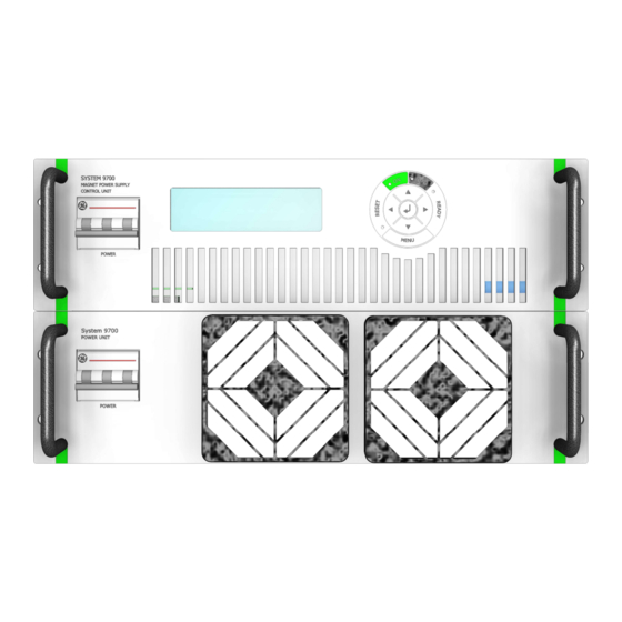
Theory of operation The SYSTEM 9700 consists of up to eight 19” 3U units each containing a number of power modules able convert the specified output power. One of the units also contains the control electronics, the local and remote interface as well as external interlocks etc. -
Page 47: System 9700 Interface Specification
System 9700 User Manual System 9700 Interface specification: The System 9700 consists of one master control units and up to eight slave power units. The combined unit has following external connections: REMOTE control Interface, D-sub 25 pole female. LOCAL control interface, D-sub 9 pole female. -
Page 48: Ac Mains Connector X1
5.1.1. AC Mains connector X1: The power connector for 400VAC mains and 230VAC control input Pin no: Name Description & Specification Main power 400 VAC 3-phase AC main input, L1 400 VAC 3-phase AC main input, L2 400 VAC 3-phase AC main input, L3 Control power 230 VAC Control input, Phase... -
Page 49: Connections For Control Unit Only
System 9700 User Manual ON/OFF 5 V Logic Level - CMOS, NMOS, and TTL compatible Spare I-SET PARALLEL Regulation Loop output for slave(s) CurrentFBLink Current feedback from slave(s) GNDA Analog GND UnderVoltage interlock Under Voltage Interlock from slave(s) Vset 0-10V... -
Page 50: Remote Control X7 (D-Sub 25 Pole)
5.2.2. REMOTE CONTROL X7 (D-SUB 25 Pole): Remote, RS232, RS422, RS485 DB25 serial line Interface Pin no: Name Description & Specification RS232 Transmitter line. RS232 Receiver line. RETURN Return line for RS232 Tx High RS422/485 Transmitter positive line. Tx Low RS422/485 Transmitter negative line. -
Page 51: Relay Extension Board (Optional)
System 9700 User Manual Interlock connections 5.2.4. Relay Extension Board (Optional) Counterpart for connector is Phoenix FMCD 1,5/9-ST-3,5 Pin no: Name Description & Specification 1 top SUM-INTL SUM Interlock SUM-INTL SUM Interlock 1 Bottom 2 top LOC-REM Local/Remote 2 bottom... -
Page 52: Maintenance
Maintenance Introduction 6.1. Servicing DANFYSIK Magnet Power Supply should be attempted only by personal trained by DANFYSIK. Dangerous voltages capable of causing loss of life are present inside this power supply. Use extreme caution when accessing, handling, testing and adjusting. -
Page 53: Troubleshooting
PHASE FAIL INTERLOCK: Check all phases. Check AC main power voltage REGULATION FAILURE INTERLOCK: Failure on regulation board or AUX-supply, contact DANFYSIK Service. MPS OVER TEMPERATURE INTERLOCK: Check ambient temperature: Temperature higher than 40 °C: Ambient temperature must drop. -
Page 54: Appendix: 9700 Mounted In Rack
The Rack can hold up to 9 System 9700 modules in total. Depending on the output current, each MPS unit will be either a single master unit (with Display) or a master with slave units (without display) placed below the master unit. - Page 55 System 9700 User Manual Input: Each System 9700 has a connection for mains input and auxiliary power. Those are combined in terminal blocks, behind the front panel in bottom of the rack. Only one 3-hase mains input supply cable is needed:...
- Page 56 Picture is for indication only, and will might differ from actual supply. Water: If water cooled System 9700 units are used, a common is placed below in the rack on the back side. The water connection is ½ inch RG...
Need help?
Do you have a question about the 9700 and is the answer not in the manual?
Questions and answers