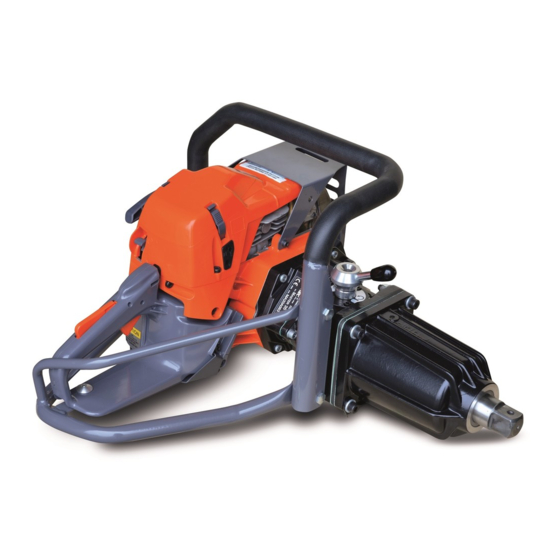
Airtec MASTER 35 Maintenance Manual
Petrol/gasoline impact wrench
Hide thumbs
Also See for MASTER 35:
- Maintenance manual (25 pages) ,
- Manual (24 pages) ,
- Manual (25 pages)
Advertisement
Table of Contents
Advertisement
Table of Contents

Related Manuals for Airtec MASTER 35


Summary of Contents for Airtec MASTER 35
- Page 1 ® MASTER 35 PETROL/GASOLINE IMPACT WRENCH Couper Street, Glasgow G4 0DL United Kingdom Tel: 44 (0) 141 552 5591 Fax: 44 (0) 141 552 5064 E-mail: enquiries@airtecintl.co.uk This full Manual can be downloaded from our website www.airtecinternational.com English, French, German & Spanish...
-
Page 2: Table Of Contents
® MASTER 35 PETROL/GASOLINE IMPACT WRENCH MAINTENANCE MANUAL CONTENTS DESCRIPTION PAGE NUMBER Uses & Technical Information Safety Precautions Operating Controls - Illustrations Operating Controls - Instructions for use Start/Stop Operation Routine Service Dismantling Motor Motor Parts List and Exploded Diagrams... - Page 3 1. USES The Master Impact Wrench is ideal for removing/fitting Chairscrews (Lag Screws) and Fishplates (Joint Bars) where track possession is not possible, i f there are access difficulties or if other sources of power e.g. Air Compressors, Generators or Power Packs are not available. The Master can drill holes in Wooden Sleepers (Ties) using our Safety Quick Release Attachment which allows the fitting/removal of Auger Bits in seconds.
-
Page 4: Safety Precautions
3. SAFETY PRECAUTIONS BEFORE using the Impact Wrench read these safety instructions CAREFULLY and ensure you fully UNDERSTAND them. DO NOT allow untrained personnel to use the Wrench. Wear suitable PROTECTIVE CLOTHING, Check pull cord is not frayed nor worn. safety boots, goggles, gloves and ear protection according to Company rules, Know where the controls are and how to... -
Page 5: Operating Controls - Illustrations
4. OPERATING CONTROLS (1) ON/OFF CONTROL SWITCH (5) THROTTLE TRIGGER (9) TORQUE SETTING LEVER (2) FUEL PRIMER BULB ON/OFF CONTROL SWITCH (6) HALF SPEED LEVER THROTTLE TRIGGER (10) OIL FILLER PLUG ( 1 ) ( 5 ) ( 9 ) TORQUE SETTING LEVER (3) CHOKE LEVER (7) FORWARD/REVERSE/... - Page 6 5. OPE RATI N G CO NTRO LS (See Page 3 for easy i d e n ti fi c a ti o n ). 1. ON/OFF CONTROL SWITCH 8. SOCKET SQUARE DRIVE move the switch to Standard 1 inch Square Drive. The Accessory START, move to is secured to the Square Drive by a Rubber...
-
Page 7: Start/Stop Operation
6. START/STOP OPERATION FUEL MIXTURE STOPPING THE WRENCH Mix = 1:25 Mineral or 1:50 Synthetic Oil to Release throttle trigger and let Motor return unleaded Petrol/Gasoline. Mix Oil and to idle. Petrol/Gasoline thoroughly in a Turn off Motor by moving ON/OFF Switch separate container before filling the tank. -
Page 8: Routine Service
7. ROUTINE SERVICE (See Exploded Diagram Drawings on Pages 8, 9, 10, 14 & 16 GREASING HAMMER AND ANVIL REPLACING SPARK PLUG 4000.0809 6. Remove four Screws 90, 91, 95, Nuts 62 and Loosen two Filter Cover Screws 0180 and lift off Nose Casing. -
Page 9: Dismantling Motor
8 . DISMANTLING MOTOR (See Exploded Diagram Drawings on Pages 8, 9, 10, 14 & 16 1. REPLACE AIR FILTER 4003.0451 7. REMOVING THE CARBURETTOR Unfasten two Screws 0180 on Filter Cover 4003.0510 0990 and lift off. Remove and replace Air Remove two Screws 0080, Screw 0720 and Fuel Filter. - Page 10 MASTER MOTOR PARTS LIST TOP COVER AND AIR FILTER STARTER ASSEMBLY Part. No. Description Part. No. Description 2870 1100 Top Cover Complete 4003 0040 (See Note 4, Page 12 4000 0880 Washer (2) 4003 0070 Washer (50.00361) 4003 0080 Screw (2) 4003 0095 Screw (2) 4003 0180...
- Page 11 10. MASTER MOTOR PARTS LIST CYLINDER & PISTON CARBURETTOR 2650 0060 Throttle Stop (AT version) Part. No. Description 2300 0520 Screw (5) (AT version) 4003 0000 2400 1050 Washer (5) (AT version) 4003 0010 Screw (33.00202) 4000 0378 Bearing (2) 4003 0020 Screw (33.00209)
- Page 12 11. MASTER MOTOR PARTS LIST CRANKCASE & FUEL TANK Part. No. Description 135596 Screw M5 x 25 2303 0315 Screw (2) (AT version) 2650 1010 Bulb Protector 2800 0001 Fuel Tank Complete Assy. 3333 3334 Backing Plate 4000 0880 Washer (11) 4000 0378 Bearing (2) 4000 8770 Screw (4) 1175...
- Page 13 Rubber Mount (4) 2650.2000 Bracket 5400563 Rubber Mount Washer (2) 2580.0080 Screw (2) 2305.0620 Screw (2) Last Serial No. for STANDARD Master 35 ATD 00A44 approximately December 1999 First Serial No. for NEW Master 35 ATE 99A01 approximately January 2000...
- Page 14 7. Piston Assembly 4003.1120. When ordering please advise the type e.g. A, B, C or D. This can be found on top of the cylinder. 8. STANDARD MASTER 35 Impact Wrench can be converted into new style using Motor Conversion Kit Part No. 2810.10 9.
-
Page 15: Dismantling Impact Unit
14. DISMANTLING IMPACT UNIT (See Exploded Diagram Drawings on Page 16). REMOVING CLUTCH SUPPORT DISMANTLING HAMMER COMPLETE FLANGE 18 Remove Gear Selector 46 and empty oil Place complete Hammer length ways in a from Gearbox 30. Remove six Screws vice with one hole uppermost. Carefully holding Clutch Support Flange to Gearbox tighten vice until Steel Ball 76 drops out of and pull apart. - Page 16 MASTER IMPACT PARTS LIST Note : Fastener torques shown on Page 17...
- Page 20 MOTOR & GEARBOX PARTS LIST DRG. PART DESCRIPTION DRG. PART DESCRIPTION DRG. PART DESCRIPTION REF. REF. 2810.1030 Motor Complete 135515 Screw 135513 Washer 2570.0050 Cam with Shaft 035514 Gasket 035107 Gear Change Knob 2510.0030 Regulator Spring 035554 Pin (2) 135110 Bevel Washer 035588 Torque Control Lever...
-
Page 21: Impact Unit & Carrying Handle
MASTER IMPACT PARTS LIST Note : Fastener torques shown on Page 17 IMPACT UNIT & CARRYING HANDLE PARTS LIST DRAWING PART DESCRIPTION DRAWING PART DESCRIPTION REF . REF . 035303 Ring Flange complete 035301 Nose Casing complete 135558 Bearing 033005 Nose Bush with 'O' Ring 035561 Ring Flange... - Page 22 MASTER IMPACT & GEARBOX UNIT NOTES FASTENER INFORMATION & TORQUES See drawings on Pages 14 and 16. Pos Screw Head Removal Torque Settings Notes Sizes Direction Ft./lbs. 13mm 19mm 13mm Loctite 243 Loctite 243 Hot Motor Muffler Impact Unit Complete 2870.0650 Toolkit 1140.1010 The Toolkit contains the following.
-
Page 23: Roll Bar Handle Kit
D r i l l 8 mm ( 5 / 1 6 ” ) p a y i n g a t t e n t i o n t o h o l d t h e D r i l l Bit perpendicular to the Carrying Handle. How to fit the Handle to the Master 35 (with 8mm – 5 / 1 6 ” h o l e ) -
Page 24: Fault Finding
20. FAULT FINDING PROBLEM POSSIBLE CAUSE ACTION MOTOR WILL NOT START 1) Empty fuel tank Open fuel tank carefully to release any pressure and fill tank. Drain tank and fill with correct 2) Incorrect fuel/oil mix mixture Set to I . 3) Control switch in stop position Set to Start position. -
Page 25: Workshop Equipment
21. WORKSHOP EQUIPMENT 4000.0308 FLYWHEEL PULLER... -
Page 26: Accessories
22. ACCESSORIES 1. METAL CARRYING BOX Strong Metal Carrying Box with full length hinged lid, lockfast fitting, twin carrying handles and anti-slip rubber base. Holds an Impact Wrench, Sockets, Augering Attachment, Bits, Clips and Oil Weight 12.04 Kgs Dimensions 590 x 455 x 296mm “... - Page 27 REFERENCE Accessories Auger Bits 22.3 Impact Sockets 22.2 Metal Carrying Box 22.1 Safety Quick Release Augering Attachment 22.3 Dismantling Impact Unit Clutch & Motor Flange 14.2 Clutch Support Flange 14.1 Gearbox 14.4 Hammer Complete 14.5 Seal & Bearings in Clutch 14.3 Dismantling Motor Air Filter...
- Page 28 REFERENCE Roll Bar Handle Kit 2800.4045 Routine Service Air Filter Fuel Filter Gearbox Oil Grease Hammer & Anvil Starter Cord Routine Maintenance Instructions Spark Plug Safety Precautions Start/Stop Operations Fuel Mixture Operating the Wrench Preparation for Start-up Re-fuelling Starting Wrench Stopping the Wrench Tuning Technical Information...
- Page 29 Couper Street, Glasgow G4 0DL United Kingdom Tel: 44 (0)141 552 5591 Fax: 44 (0) 141 552 5064 E-mail: enquiries@airtecintl.co.uk Website: www.airtecinternational.com...
Need help?
Do you have a question about the MASTER 35 and is the answer not in the manual?
Questions and answers