Advertisement
Quick Links
©#&RS\ULJKW#(XURWKHUP#'ULYHV#/LPLWHG#4<<<
All rights strictly reserved. No part of this document may be stored in a retrieval system, or transmitted
in any form or by any means to persons not employed by a Eurotherm group company without written
permission from Eurotherm Drives Ltd.
Although every effort has been taken to ensure the accuracy of this document it may be necessary,
without notice, to make amendments or correct omissions. Eurotherm Drives cannot accept
responsibility for damage, injury, or expenses resulting therefrom.
3ULQWHG#LQ#(QJODQG
934
3URGXFW#0DQXDO
+$79784;
( 8 5 2 7 + ( 5 0
' 5 , 9 ( 6
,VVXH
6
Advertisement

Related Manuals for Eurotherm 601


Summary of Contents for Eurotherm 601
- Page 1 All rights strictly reserved. No part of this document may be stored in a retrieval system, or transmitted in any form or by any means to persons not employed by a Eurotherm group company without written permission from Eurotherm Drives Ltd.
- Page 2 :$55$17< Eurotherm Drives warrants the goods against defects in design, materials and workmanship for the period of 12 months from the date of delivery on the terms detailed in Eurotherm Drives Standard Conditions of Sale IA058393C. Eurotherm Drives reserves the right to change the content and product specification without notice.
- Page 3 $33/,&$7,21#5,6. The specifications, processes and circuitry described herein are for guidance only, and may need to be adapted to the user’s specific application. Eurotherm Drives does not guarantee the suitability of the equipment described in this Guide for individual applications.
- Page 4 (1&/2685( (1&/2685( (1&/2685( (1&/2685( To maintain compliance with the Standard VDE0160(1994)/EN50178(1998) (used to demonstrate the 601 compliance with the Low Voltage Directive) the unit should be mounted inside a suitable control cubicle requiring a tool for opening. 5&'V 5&'V 5&'V 5&'V...
- Page 5 &RQWHQWV 3DJH &KDSWHU#4#3URGXFW#2YHUYLHZ 'HVFULSWLRQ1111111111111111111111111111111111111111111111111111 404 (TXLSPHQW#6XSSOLHG 111111111111111111111111111111111111111 404 /('#'LVSOD\111111111111111111111111111111111111111111111111111 406 )XQFWLRQ#.H\V 111111111111111111111111111111111111111111111111 406 ,QVWUXFWLRQ#3XOORXW#*XLGH111111111111111111111111111111111 407 &RQWURO#7HUPLQDO#'HVFULSWLRQ 11111111111111111111111111 407 3RZHU#7HUPLQDO#'HVFULSWLRQ 1111111111111111111111111111 408 &RQWURO#&DEOH#5HWDLQHU11111111111111111111111111111111111 408 0RWRU#&DEOH#&ODPS 111111111111111111111111111111111111111 408 &ORQLQJ#&RQQHFWRU 1111111111111111111111111111111111111111 408 &KDSWHU#5#7HFKQLFDO#'HWDLOV (OHFWULFDO#6SHFLILFDWLRQ 111111111111111111111111111111111111 504 (QYLURQPHQWDO#6SHFLILFDWLRQ 1111111111111111111111111111 505 0HFKDQLFDO#6SHFLILFDWLRQ 11111111111111111111111111111111 505 &KDSWHU#6#3URGXFW#&RGH &KDSWHU#7#(OHFWULFDO#,QVWDOODWLRQ :LULQJ#*XLGHOLQHV#IRU#(0&...
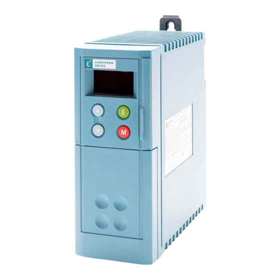
- Page 6 RFI filters. A pullout instruction guide provides quick reference for LED codes and terminal description. Suitable members of the 601 range can operate from either a single phase two wire supply of 220/240 Volts or 3 wire 380 - 460 Volts supply, 50/60Hz.
- Page 7 4#0#5 3URGXFW#2YHUYLHZ# (8527+(50 '5,9(6 7R#UHPRYH#7HUPLQDO#&RYHU#SUHVV#KHUH#DQG#SXOO#GRZQ '%54 '%55 &ORQLQJ#FRQQHFWLRQ +LQWHUQDO, (8527+(50 '5,9(6 /('#'LVSOD\ ,QVWUXFWLRQ 3XOORXW#*XLGH )XQFWLRQ .H\V &RQWURO 4 5 6 7 < 7HUPLQDOV 3RZHU 7HUPLQDOV 6XSSO\#3( &DEOH 5HWDLQHU 4#3KDVH 4#3KDVH 4#3KDVH 4#3KDVH L2/N 6#3KDVH 6#3KDVH 6#3KDVH 6#3KDVH M1/U M1/U M2/V M2/V M3/W M3/W...
-
Page 8: Status Level
4#0#6 ##3URGXFW#2YHUYLHZ /('#',63/$< Three seven segment LED displays provide drive programming, status and diagnostic values. Refer to the following tables for further information: • Table 5.1 for User Adjustable Parameters description (pages 5-1 and 5-2). • Table 5.2 for Drive Status description (page 5-5). •... - Page 9 4#0#7 3URGXFW#2YHUYLHZ# ,16758&7,21#38//287#*8,'( This panel gives the user sufficient information for basic operation of the product: • Translates the drive status information given in mnemonic form on the LED display (eg RDY = Ready; OC = Overcurrent). • Decodes the titles of the parameters (P1 to P15) and the diagnostics (D1 to D3) shown on the LED display (eg D1 = Frequency).
- Page 10 This connector is located between the first and second top rib. It is intended to mate with an external data module. In order for the cloning function to operate, a compatible data module must be present (refer to Eurotherm Drives Sales Department).
- Page 11 5#0#4 7HFKQLFDO#'HWDLOV## (&+1,&$/# (7$,/6 (/(&75,&$/#63(&,),&$7,21 3$5$0(7(5 5532573#9#“#43(##4#3KDVH#+,7271,- 81,76 316:N:2 3188N:2 31:8N:2 414N:2 418N:2 318KS 31:8KS 413KS 418KS 0D[#6XSSO\ $PSV#$& 91< <18 4513 4813 &XUUHQW#4SK +506, 6XSSO\#)XVH#5DWLQJ $PSV 43#[#6;#PP (DUWK#/HDNDJH &XUUHQW#+)LOWHUHG, 0D[#2XWSXW $PSV#$& &XUUHQW###73 & 0D[#2XWSXW $PSV#$& &XUUHQW###83 & +HDW#'LVVLSDWLRQ :DWWV 6;32793#9#“#43(##6#3KDVH#+,7271,- 316:N:2 3188N:2...
- Page 12 The 601 must be mounted vertically on a solid flat non-inflammable vertical surface either panel mounted or on a rail complying with EN50022 (35mm DIN). The unique dual action clip allows the 601 to be easily panel or DIN rail mounted. (1*/,6+...
- Page 13 7DEOH#516 9HQWLODWLRQ In normal operation the 601 dissipates heat and must therefore be mounted to allow the free flow of air vertically through the ventilation slots and heatsink. Care must be taken to ensure that the mounting surface is cool and that heat generated by other adjacent equipment is not transmitted to the 601.
- Page 14 GR = German IT = Italian SP = Spanish US = American English Livery 00 = Eurotherm Standard Livery Internal RFI Filter 0 = No Filter F = Filter Fitted AC Supply Voltage +/- 10 % 230 = 220 / 240 V AC 1-Phase...
- Page 15 Read the Safety Information at the front of the manual before proceeding. :,5,1*#*8,'(/,1(6#)25#(0& The 601 series has been designed to comply with the European Community Directive 89/336/EEC on EMC. In particular the 601 meets the given generic emission and immunity standards specified in table 2.2 when suitably cubicle mounted and when the internal RFI filter option is fitted.
- Page 16 Connect the screen to earth at the 601 end only (see figure 4.3). Note the cubicle must provide 15dB attenuation to radiated emissions between 30 and 100MHz to meet the residential limits.
- Page 17 7#0#6 (OHFWULFDO#,QVWDOODWLRQ## by using two independent protective earth incoming supply conductors (figure 4.3). This is due to the high earth leakage current when using filters. The incoming mains supply should be protected by a suitable fuse or circuit breaker, as shown in table 2.1. Current Rating Cable size Cable size...
- Page 18 7#0#7# (OHFWULFDO#,QVWDOODWLRQ The terminal used to control the speed of the motor depends on the setting of Parameter P13 Setpoint Select as shown in Table 4.2 below: 3DUDPHWHU &RQWURO &RQWURO 6HWSRLQW#6RXUFH 7HUPLQDO#; 7HUPLQDO#< Control Terminal 2 (0-10V) - forward Jog Speed (set by Parameter P8) - forward Control Terminal 2 (0-10V) - reverse Jog Speed (set by Parameter P8)- reverse Control Terminal 3 (4-20mA) - forward...
- Page 19 7#0#8 (OHFWULFDO#,QVWDOODWLRQ## 7HUPLQDO#7LJKWHQLQJ#7RUTXH Terminals using automatic cage clamps are provided. Tightening torque is not applicable. ,QWHUQDO#2YHUORDG#3URWHFWLRQ These devices provide Class 10 motor overload protection. The maximum internal overload protection level (current limit) is 150% for 30 seconds. Refer page 5-1 for user current limit adjustment information.
- Page 20 WITH SHORT TERM STOPPING OR BRAKING ONLY. IT IS NOT RATED FOR A CONTINUOUSLY OVERHAULING LOAD. All 601 units are supplied without braking resistors. The following paragraphs should be used as a guide to calculate the braking requirements of the system.
- Page 21 However, it may be necessary to change some Parameters to suit individual installations (see Chapter 1). Parameters Base Frequency (P7), and Bit Parameters (P11-P15) cannot be changed when the motor is running. No Parameter (P1-P15) can be changed when the 601 is in Local Mode. 86(5#$'-867$%/(#3$5$0(7(56...
- Page 22 8#0#5## 2SHUDWLQJ#'HVFULSWLRQ 7LWOH 7UDQVODWLRQ 'HVFULSWLRQ 5DQJH )DFWRU\ 'HIDXOW 3å %DVH 7KH#RXWSXW#IUHTXHQF\#DW 580573#+] 83293+] )UHTXHQF\ ZKLFK#PD[LPXP#YROWDJH#LV +VHH#604, UHDFKHG1 Sä -RJ#6SHHG 7KH#VSHHG#DW#ZKLFK#WKH#934 30573#+] 43+] ZLOO#UXQ#LI#&RQWURO#7HUPLQDO +3UHVHW#5, <#LV#KLJK 3ã 3UHVHW#6SHHG#6 7KH#VSHHG#DW#ZKLFK#WKH#934 30573#+] 58+] ZLOO#UXQ#ZKHQ#346# #5/ &RQWURO#7HUPLQDO#;#LV#ORZ DQG#&RQWURO#7HUPLQDO#<#LV KLJK 3ëì 3DVVZRUG $#SDVVZRUG#PD\#EH#VHW#WR 3#0#<<< SURKLELW#XQDXWKRULVHG DGMXVWPHQW#RI#3DUDPHWHUV1 :KHQ#343#LV#VHW#WR#QRQ0 ]HUR#WKH#XVHU#ZLOO#EH...
- Page 23 8#0#6 2SHUDWLQJ#'HVFULSWLRQ## 39#9ROWDJH#%RRVW This is used to correctly flux the motor at low speeds. This allows the drive to produce greater starting torque for high friction loads. The VOLTAGE BOOST parameter increases the motor volts above the selected V/F characteristic at the lower end of the speed range.
- Page 24 This parameter will always display zero when the value level is first entered. Selecting Mode 1 (by pressing once then pressing will copy a configuration to the 601 from a compatible external device. Selecting Mode 2 (by pressing twice then pressing will copy the current 601 configuration to a compatible external device.
- Page 25 8#0#8 2SHUDWLQJ#'HVFULSWLRQ## '5,9(#67$786 7LWOH 'HVFULSWLRQ 3RVVLEOH#&DXVH 5($'<2+($/7+<#+1R#$ODUPV#3UHVHQW,1 Ramp Up 7LPH# # # # WRR#VKRUW#IRU#LQHUWLD#RI 29(5&855(171 ORDG#DQG2RU#SRZHU#UDWLQJ#RI#9341 93423362563#0#934233:2563 55$ Ramp Down 7LPH#WRR#VKRUW#IRU#LQHUWLD#RI 93423362733#0#93423482733 55$ ORDG#DQG2RU#SRZHU#UDWLQJ#RI#9341 93423442563#0#93423482563 77$ $SSOLFDWLRQ#RI#VKRFN#RYHUORDG1 93423552733 6KRUW#FLUFXLW#EHWZHHQ#PRWRU#SKDVHV1 6KRUW#FLUFXLW#IURP#PRWRU#SKDVH#WR#HDUWK1 0RWRU#FDEOHV#WRR#ORQJ#RU#WRR#PDQ\ SDUDOOHO#PRWRUV1 Voltage Boost VHW#WRR#KLJK1 ûRX 29(592/7$*(1##'&#EXV#YROWDJH 7KH#VXSSO\#YROWDJH#LV#WRR#KLJK1 H[FHHGHG#743#9#GF1#+;43#9#GF#IRU#733 Ramp Down 7LPH# # # # WRR#VKRUW#IRU#ORDG 9#60SKDVH#YHUVLRQ,1 LQHUWLD2SRZHU#UDWLQJ1 ,#[#W#29(5/2$'1##&XPXODWLYH#RYHUORDG...
- Page 26 P14 = 0. This places the product into a state where the RUN command can be re-applied and if the alarm does not reoccur the product will run normally. 5HVHW#WR#)DFWRU\#'HIDXOW#9DOXHV All parameters can be returned to factory default settings by powering up the 601 while both keys are pressed simultaneously. ',$*1267,&6...
- Page 27 NO EMC 'CE'MARK APPLIED TO E.D MODULE EN50081-1(1992) AND/OR EN50081-2(1994), AND EN50082-1(1992) (AND prEN50082-2(1992)). RELEVANT APPARATUS E.D. = EUROTHERM DRIVES LIMITED MANUFACTURER/SUPPLIER/INSTALLERS RESPONSIBILITY TO CONFORM WITH EMC DIRECTIVE. E.D. EMC CHARACTERISTICS AND MANUFACTURERS DECLARATION MAY BE USED AS A BASIS IN THE OVERALL PRODCT JUSTIFICATION )LJXUH#914##(XURWKHUP#(0&#¶&(·#0DUN#9DOLGLW\#&KDUW...
- Page 28 (3$,5 0$,17(1$1&( Routine maintenance of the 601 comprises a periodic inspection to check for a build- up of any dust, or other obstructions, that may affect the ventilation of the unit. Obstructions should be removed and any dust must be cleared using dry air.
- Page 29 All rights strictly reserved. No part of this document may be stored in a retrieval system, or transmitted in any form or by any means to persons not employed by a Eurotherm group company without written permission from Eurotherm Drives Ltd.
- Page 30 02',),&$7,21 (&1 '$7( '5$:1 &+.*' ,QLWLDO#,VVXH#+$79784; 45498 5;1351<; ,QWURGXFWLRQ#RI#7339#60SKDVH#UDQJH#DQG 9HUVLRQ#5#6RIWZDUH1 3DJH#505#DGGHG#48P#PRWRU#FDEOH#WR 45;9; 6413:1<; 5339#414N:#DQG#418N:1 &RUUHFWLRQV#WR#*HUPDQ#WUDQVODWLRQ#RQ 45<<8 4<13;1<; SDJHV#407/##705/#708/#709/#DQG#8091 5HSODFHG#SU(1834:;+4<<8,#ZLWK (1834:;+4<<;,#DQG#XSGDWHG#(& 'HFODUDWLRQ#RI#&RQIRUPLW\1 46447 5HPRYHG#DGGUHVV#OLVW#IURP#LQVLGH#PDQXDO WR#EDFN#FRYHU1 46497 *HUPDQ#YHUVLRQ#SDJH#504#FRUUHFWHG#4 SKDVLJ#WR#6#SKDVLJ#DQG#VSHOOLQJ FRUUHFWLRQV#RQ#SDJHV#809/#708#DQG#7091 464:7 ;1341<< &0 ),567#86('#21 02',),&$7,21#5(&25' #934#3URGXFW#0DQXDO '5$:,1*#180%(5 6+71#4 (8527+(50#'5,9(6 ==79784; 2)##4...
Need help?
Do you have a question about the 601 and is the answer not in the manual?
Questions and answers