Viking VCWB300 Installation Manual
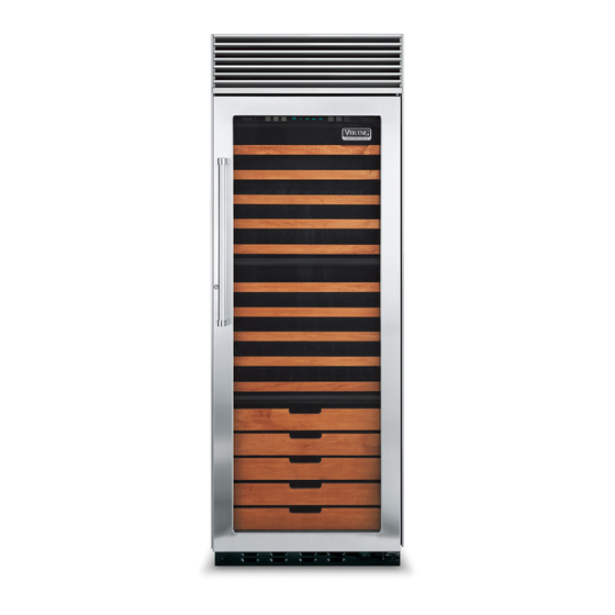
Built-in full height wine cellar
Hide thumbs
Also See for VCWB300:
- Service notebook (24 pages) ,
- Brochure & specs (64 pages) ,
- Product brochure (56 pages)
Table of Contents
Advertisement
Quick Links
Advertisement
Table of Contents

Related Manuals for Viking VCWB300


Summary of Contents for Viking VCWB300
- Page 1 Viking Installation Guide Viking Range Corporation 111 Front Street Greenwood, Mississippi 38930 USA (662) 455-1200 For product information, call 1-888-VIKING1 (845-4641) or visit the Viking Web site at vikingrange.com Built-In Full Height Wine Cellar F20383C EN (032410)
-
Page 2: Important - Please Read And Follow
3/4” (1.9 • Viking Range Corporation will NOT warranty any problems resulting from GFI outlets which cm) into room. are not installed properly or do not meet the requirements below. - Page 3 FEATURES OF YOUR WINE CELLAR SITE PREPARATIONS AND CONSIDERATIONS PROFESSIONAL MODEL 30” W. FULL HEIGHT WINE CELLAR CABINET OPENING DIMENSIONS 1. TriTemp™ storage system 8. High temperature alarm (behind grille) 2. Electronic control center 9. Door alarm (behind grille) 3. Convertible display shelves (2) 10.
-
Page 4: Electrical Requirements
SITE PREPARATIONS AND CONSIDERATIONS AREA REQUIREMENTS DESIGNER/FULL OVERLAY MODEL 30” W. FULL HEIGHT WINE CELLAR V V e e r r i i f f y y t t h h e e f f o o l l l l o o w w i i n n g g : : CABINET OPENING DIMENSIONS •Wine cellar can fit into residence and can be moved around corners and through doorways. - Page 5 WINE CELLAR OVERALL DIMENSIONS - PROFESSIONAL MODEL CABINET INFORMATION - PROFESSIONAL MODEL Professional models fit “semi-flush” in standard 24” (61.0 cm) deep cabinet openings. The door face protrudes 2-5/16” (5.9 cm) from the cabinet face. The handle protrudes an additional 2-1/2” (6.4 cm) into the room 29-1/2”...
-
Page 6: Right Side Panel
CABINET INFORMATION - PROFESSIONAL (continued) CUSTOM SIDE PANEL DIMENSIONS - PROFESSIONAL MODEL For 3/4” (1.9 cm) Side Panels 29-1/2” (90.2 cm) Wall 3/4” (1.9 cm) THICK END PANEL 3/16” 3/16” 3/16” (0.5 cm) (0.5 cm) (0.5 cm) 22-3/8” 22-3/8” THICK BACK (56.9 cm) (56.9 cm) FILLER PANEL... - Page 7 WINE CELLAR OVERALL DIMENSIONS - DESIGNER MODEL CABINET INFORMATION - DESIGNER MODEL SIDE VIEW Designer models fit “flush” in standard 24” (61.0 cm) deep cabinet openings with no protrusion into the room except TOP VIEW 24-1/32” (61.0 cm) 29” (73.7 cm) 2-1/2”...
-
Page 8: Top View
CABINET INFORMATION - DESIGNER (continued) OVERALL DIMENSIONS - FULL OVERLAY MODEL 24-3/4” (62.9 cm) SIDE VIEW TO FRONT OF GRILLE 30” (76.2 cm) 29” (73.7 cm) TOP VIEW WALL 3/4” (1.9 cm) SPACE IF 24” (61.0 cm) 1/8” 4-17/32” 1-9/32” STANDARD CABINET DEPTH IS USED (0.3 cm) (11.5 cm) - Page 9 CABINET INFORMATION - FULL OVERLAY MODEL CABINET INFORMATION - FULL OVERLAY (continued) Full overlay models, (with 3/4” [1.9 cm] thick panels and custom handles locally supplied), fit flush in 25” (63.5 cm) Full overlay models can be installed in standard 24” (61.0 cm) deep openings. However, the door faces and top deep (countertop depth) cabinet openings with no protrusion into room except custom handles.
- Page 10 CUSTOM SIDE PANEL DIMENSIONS - DESIGNER/FULL OVERLAY CUSTOM DOOR PANEL DIMENSIONS - FULL OVERLAY MODEL For 3/4” (1.9 cm) Side Panels NOTE: Adding a 3/4” (1.9 cm) side panel adds an additional 3/4” (1.9 cm) to the overall width of the product for each side panel used. Requires side panel hardware kit (Kit model number - SPHK S) Z-BRACKET 1”...
- Page 11 DOOR PANEL INSTALLATION - FULL OVERLAY MODEL CUSTOM WOOD FACINGS DIMENSIONS Each wine rack has a wood facing which can be removed. The facings can be stained, painted, or removed and replaced with alternative wood facings. NOTE: A scrap sample should be tested in the unit before attaching permanent Panels must not weigh more than 50 pounds per door.
-
Page 12: Wine Cellar Installation
WINE CELLAR INSTALLATION HOME SECURITY SYSTEM CONNECTION WARNING T T I I P P O O V V E E R R H H A A Z Z A A R R D D N N O O T T E E : : Contact a qualified electrician or authorized agent from alarm company to connect your home security system WARNING W W i i n n e e c c e e l l l l a a r r i i s s t t o o p p h h e e a a v v y y a a n n d d t t i i p p s s e e a a s s i i l l y y to the wine cellar. - Page 13 Before moving the wine cellar in place, WARNING confirm the finished dimensions, electrical E E l l e e c c t t r r i i c c a a l l S S h h o o c c k k H H a a z z a a r r d d location, minimum door and shelf clearances, D D i i s s c c o o n n n n e e c c t t p p o o w w e e r r a a t t b b r r e e a a k k e e r r o o r r t t u u r r n n p p o o w w e e r r d d i i s s c c o o n n n n e e c c t t s s w w i i t t c c h h and door panel instructions.
-
Page 14: Kickplate Installation
KICKPLATE INSTALLATION The kickplate consists of a two (2) part assembly: one top louvered panel and one bottom solid panel. Install the kickplate with louvered section on the top. Flooring must allow the kickplate to be removed. See “Site Preparations” for height clearance (pages 5 and 6).