Advertisement
Quick Links
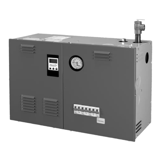
M
ONITRON II
MODEL EH-M2 ELECTRIC BOILER
Four stage electronic control with energy saving and other features.
EH-08-135-M2 through EH-40-135-M2, single phase, 3 wire, 120/208V, 120/240V
EH-12-345-M2 through EH-40-345-M2, three phase, 4 wire, 120/208V, 120/240V
OPERATION AND INSTALLATION INSTRUCTIONS
CONTENTS . . . . . . . . . . . . . . . . . . . . . . . . . . . . . . . . . . . .PAGE
Description . . . . . . . . . . . . . . . . . . . . . . . . . . . . . . . . . . . . . . . . .2
Mounting . . . . . . . . . . . . . . . . . . . . . . . . . . . . . . . . . . . . . . . . . . .2
Piping . . . . . . . . . . . . . . . . . . . . . . . . . . . . . . . . . . . . . . . . . .2 & 4
Air Eliminator and Expansion Tanks . . . . . . . . . . . . . . . . . .2
Flow Switch . . . . . . . . . . . . . . . . . . . . . . . . . . . . . . . . . . . . .2
Bypass . . . . . . . . . . . . . . . . . . . . . . . . . . . . . . . . . . . . . . . . .2
Wiring (Warning: DO NOT turn on breakers on unit) . . . . . . . . .2
Wall Thermostat Flow Switch and Circulator . . . . . . . . . . .2
"Rough-In" Dimensions . . . . . . . . . . . . . . . . . . . . . . . . . . . .3
Service Connections and Electrical Ratings . . . . . . . . . . . .6
Electrical Connections & Sensor Locations . . . . . . . . . . . . . . . .5
Start-up . . . . . . . . . . . . . . . . . . . . . . . . . . . . . . . . . . . . . . . . . . . .7
Fill System . . . . . . . . . . . . . . . . . . . . . . . . . . . . . . . . . . . . . .7
Air Elimination . . . . . . . . . . . . . . . . . . . . . . . . . . . . . . . . . . .7
Bypass Flow Adjustment . . . . . . . . . . . . . . . . . . . . . . . . . . .7
Check for Proper Boiler and System Operation . . . . . . . . .7
Operation . . . . . . . . . . . . . . . . . . . . . . . . . . . . . . . . . . . . . . . . . .7
Periodic Inspection . . . . . . . . . . . . . . . . . . . . . . . . . . . . . . . . . . .7
Control Setup . . . . . . . . . . . . . . . . . . . . . . . . . . . . . . . . . . . . . . .8
Appendix A, B, C, & D . . . . . . . . . . . . . . . . . . . . . . . . . . . . . . . .9
Heating Contractor
Address
Phone Number
IMPORTANT:
This manual must be left with owner and should be hung
on or adjacent to the boiler for reference.
Model Number
Serial Number
Installation Date
Publication No. EH-M2-40 Rev D • Printed in U.S.A. 315
LISTED
89C4
Part No. 792860000
Advertisement

Related Manuals for Slant/Fin EH-M2


Summary of Contents for Slant/Fin EH-M2
- Page 1 Appendix A, B, C, & D ....... .9 Heating Contractor Model Number Address Serial Number Phone Number Installation Date Publication No. EH-M2-40 Rev D • Printed in U.S.A. 315 Part No. 792860000...
- Page 2 For cement walls, determine a tains a terminal board marked, (SLANT/FIN “INTERFACE location for the wall bracket to mount where the anchors will BOARD”).
- Page 3 7/8 [22] [92] 9 13/32 5 PLACES 8 23/32 [239] [222] ø 2 [51] KNOCKOUT WALL ø ø 2 1/2 [64] & 1 3/8 6 15/16 [177] KNOCKOUTS ø 2 3/16 [56](1 1/4 RETURN) EH-M2-40 Boiler Operation and Installation Instructions...
- Page 4 There should be no elbows, tees, or change of pipe size for at least 5 diameters of pipe size (see Table 2) upstream and downstream of flow switch. Flow switch should always be mounted in the horizontal position. See Table 2. EH-M2-40 Boiler Operation and Installation Instructions...
- Page 5 Sensor exchanger Relay Factory Installed Boiler Figure 5. Electrical Connections Outlet Sensor Secondary Piping Sensor (Included) Boiler Inlet Sensor (Optional) Figure 5A. Sensor Location (See EM-10 Manual for details) Figure 6. DHW Connections EH-M2-40 Boiler Operation and Installation Instructions...
- Page 6 83 † EH32-34-5-M2 96 † EH40-34-5-M2 108 † EH40-34-5-M2 125 † † Leg with the highest value of line current of an unbalanced 3-phase load. ‡ 125 VAC maximum rating of all hot conductors. EH-M2-40 Boiler Operation and Installation Instructions...
-
Page 7: Periodic Inspection
4. Water flow through the boiler should be sufficient to keep the serviceperson. flow switch closed. The limit thermostat should also remain closed. Consult the multiple stage electronic control manual for control setup. EH-M2-40 Boiler Operation and Installation Instructions... - Page 8 “Factory” position on dip switch has to be returned to “installer” position to prevent unauthorized changes to factory settings. *Local design input may vary from the example shown. Be sure to use design inputs for your geographical location. EXAMPLE SETTINGS MAY VARY ACCORDING TO ACTUAL DESIGN REQUIREMENTS. EH-M2-40 Boiler Operation and Installation Instructions...
- Page 9 The boiler warrenty does not cover leaks resulting from corrosion caused by the use of underfloor plastic tubing without an oxygen diffusion barrier. Systems must have the non-oxygen diffusion barrier tubing separated from the boiler with a heat exchanger. Slant/Fin recommends the use of underfloor plastic tubing with an oxygen diffusion barrier.
- Page 10 EH-M2-40 Boiler Operation and Installation Instructions...
- Page 11 EH-M2-40 Boiler Operation and Installation Instructions...
- Page 12 SLANT/FIN CORPORATION, Greenvale, N.Y. 11548 • Phone: (516) 484-2600 FAX: (516) 484-5921 • Canada: Slant/Fin , Mississauga, Ontario LTD/LTEE www.slantfin.com...
Need help?
Do you have a question about the EH-M2 and is the answer not in the manual?
Questions and answers