
Subscribe to Our Youtube Channel
Related Manuals for Tekram Technology P5T30-B4

Summary of Contents for Tekram Technology P5T30-B4
- Page 1 P5T30-B4 MAINBOARD User’s Manual Rev: 1.05 Date: January - 98 * All other product names are trademarks or copyrights of their respective owners.
- Page 3 The use of shielded cables for connection of the monitor to the graphics card is required to assure compliance with FCC regulations. P5T30-B4 User’s Manual...
-
Page 4: Table Of Contents
IrDA-compliant infrared module connector ............15 USB Connection....................15 Keyboard Connector..................16 PS/2 Mouse Connector ..................16 Floppy Drives....................16 IDE Hard Drives and CD-ROMs ............... 16 MAINBOARD BIOS SETUP..............17 About the BIOS....................17 Using Setup....................... 17 P5T30-B4 User’s Manual... - Page 5 SAVE & EXIT SETUP / EXIT WITHOUT SAVING........35 PCI Device Listing .................... 35 DESKTOP MANAGEMENT INTERFACE (DMI)......36 FLASH BIOS PROGRAMMING UTILITY........37 HAREWARE MONITORING UTILITY ..........38 DC-310U PCI ULTRA-SCSI ADAPTER ..........39 APPENDIX A Using the ATX Power Supply ........40 P5T30-B4 User’s Manual...
-
Page 6: Introduction
Mastering IDE and Universal Serial Bus (USB) onto the mainboard, optimum system performance is assured and system design and implementation is simplified. Fully “Plug & Play” compatible via an Award BIOS, the P5T30-B4 facilitates easy system configuration and peripheral setup. Advanced BIOS features include Temperature Monitoring and Alert functions designed to prevent the CPU from overheating. -
Page 7: Features
¾ Baby AT Form factor ( 10.6″ by 8.7″ ) IrDA interface kit (internal cable/bracket set and external module) Options USB cable/bracket set 5-in-1 cable set: FDD cable, PS/2 Mouse connector kit, Two Serial, Accessories One Parallel bracket User’s Manual, Driver/ Utility diskettes P5T30-B4 User’s Manual... -
Page 8: Board Level Features
Infrared (IR) connector power connector L2 Pipeline-burst cache Infrared (IR) connector ® ® Intel 82430TX chipset AT keyboard connector DRAM SIMM/DIMM sockets PS/2 mouse connector 10. Secondary IDE connector COM1 connector 11. Primary IDE connector USB connector P5T30-B4 User’s Manual... - Page 9 19. PS/2 MOUSE CONNECTOR: Supports PS/2 style mice. 20. COM1 CONNECTOR: High-speed UART compatible serial port. 21. USB CONNECTOR: A header connector for an optional USB (Universal Serial Bus) module is provided. This connector permits the connection of two USB peripheral P5T30-B4 User’s Manual...
-
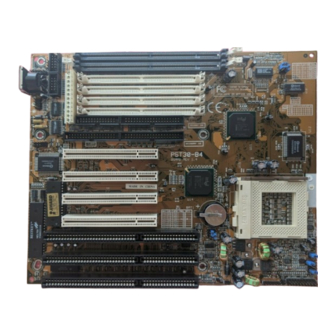
Page 10: Comprehensive Mainboard View
BOARD LEVEL FEATURES BOARD LEVEL FEATURES devices directly to the port without an external hub. USB is a new technology supporting keyboards, mouse, printers, fax modems and other telephony devices. Comprehensive Mainboard View P5T30-B4 User’s Manual... -
Page 11: Installing The Cpu And Memory
This mainboard features a fan monitoring function to alert you when the cooling fan starts to malfunction (Refer to page 27). If you are using a fan with the standard 4-pin Molex-Type Power-Supply connector, you should use the fan adaptive cable provided as shown: P5T30-B4 User’s Manual... -
Page 12: Setting The Cpu Clock Selection Jumper
Cyrix 6x86MX PR166 (M2) 133MHz 66MHz x2.0 Cyrix 6x86MX PR166 (M2) 150MHz 60MHz x2.5 Cyrix 6x86 P200+ 150MHz 75MHz x2.0 Cyrix 6x86 P166+ 133MHz 66MHz x2.0 Cyrix 6x86 P150+ 120MHz 60MHz x2.0 Cyrix 6x86 P133+ 110MHz 55MHz x2.0 P5T30-B4 User’s Manual... -
Page 13: Setting The Cpu Voltage Selection Jumper
P54C 6x86 6x86MX (M2) Vcore/Vcc 2.8V/3.3V “x” / 3.3V “x” / 3.3V “x” / 3.5V 2.9V/3.3V JP1 & JP2 (*) : See what voltage is required for your Cyrix CPU, 3.3V or 3.5V. “x” : Don care. P5T30-B4 User’s Manual... -
Page 14: Installing The Memory (Dram Simm/Dimms)
(*): See what voltage is required for your CPU. “x”: Don care. Installing the Memory (DRAM SIMM/DIMMs) • The P5T30-B4 mainboard supports 72-pin SIMMs and 168-pin DIMMs of two types: • SIMM: 5 Volt Fast Page Mode (Asymmetric or Symmetric) or EDO (Extended Data Output) •... -
Page 15: Setting The Jumpers
Jumper Cap across the two pins, thereby Pin 2-3 Short connecting them. 3-pin jumpers can be set to pins 1-2 or 2-3 connected. Pin-1 is labeled on the circuit board for these jumpers as shown: JBF0-2 JP1 & JFS0-2 P5T30-B4 User’s Manual... - Page 16 JP1 & JP2: CPU Voltage Selection Jumper - This jumper is explained in detail on page J12: CPU cooling fan connector - This jumper is explained in detail on page 9. JFS0-2: CPU Clock Selection - This jumper is explained in detail on page 10. P5T30-B4 User’s Manual...
-
Page 17: Connections
UART2 is directed, COM2 or IrDA. (* Pin-6 is reserved for consumer IR input - remote control *) USB Connector This 8-pin connector permits connection of two USB peripheral devices directly to the system without an external hub. P5T30-B4 User’s Manual... -
Page 18: Keyboard Connector
Make sure to align the RED stripe on the ribbon cable with Pin-1 on the mainboard IDE connector. On most hard drives and CD-ROMs, the RED stripe should be oriented towards the power connector of the device. P5T30-B4 User’s Manual... -
Page 19: Mainboard Bios Setup
CMOS (Complementary Metal Oxide Semiconductor) refers to the chip in which the BIOS information is stored. The P5T30-B4 mainboard features Award BIOS, which provides an easy to use Setup program to aid in hardware configuration. In this section we will look at the various menus and options contained in the Award BIOS Setup Program. -
Page 20: Main Menu
The Main Menu allows you to select from several setup functions and two exit choices. Use the arrow keys to select among the items and press <Enter> to accept and enter the sub-menu. Note that a brief description of each highlighted selection appears at the bottom of the screen. P5T30-B4 User’s Manual... -
Page 21: Standard Cmos Setup
BIOS Setup. If the device is a hard disk or CD-ROM, generally the Auto option is the best choice for fast and easy setup of the hard disk parameters. Here’s an explanation of the Auto, User and Types (1-45) options: P5T30-B4 User’s Manual... - Page 22 If you are using a hard drive that is over 528MB in capacity, but was already formatted without using LBA mode, LBA support will be ignored even if it is enabled. This assures correct access to the drive data. P5T30-B4 User’s Manual...
- Page 23 Extended Memory is the amount of memory located above 1MB in the CPU's memory address map. Other Memory refers to the memory located in the region between 640K and 1MB. This region can be used for shadowing as well as expanded memory in DOS. P5T30-B4 User’s Manual...
-
Page 24: Bios Features Setup
CPU Internal Cache - Enables or Disables the Level-1 Internal Cache memory. Generally, this would only be Disabled for troubleshooting purposes. External Cache - Enables or Disables the Level-2 External Cache memory. Generally, this would only be Disabled for troubleshooting purposes. P5T30-B4 User’s Manual... - Page 25 Boot Up NumLock Status - When On, the NumLock key will be automatically enabled when the system boots. Boot Up System Speed - Sets the system speed to High or Low. Generally, low speed would only be used for troubleshooting purposes. P5T30-B4 User’s Manual...
- Page 26 The contents of C0000h-C7FFFh are written to the same address in system memory (RAM) for faster execution. Disabled The video ROM is not copied to RAM. The contents of the video ROM cannot be read from or written to cache memory. P5T30-B4 User’s Manual...
-
Page 27: Chipset Features Setup
DRAM Timing - DRAM timing is controlled by the DRAM timing registers. The timings programmed into this register are dependent on the system design. 60ns is the fastest rate. The 70ns timing is slower and may be required in certain system designs to support loose layouts or slower memory. P5T30-B4 User’s Manual... - Page 28 System BIOS addressed at F0000H to FFFFFH to be cached. *Disabled is the default. Video BIOS Cacheable - When Enabled, the Video BIOS cacheable will cause access to the video BIOS addressed at C0000H to C7FFFH to be cached. *Enabled is the default. P5T30-B4 User’s Manual...
- Page 29 CPU Fan Malfunction Alarm - When Enabled, the system will issue a warning via the speaker when the CPU fan starts to malfunction. System 5V Alarm (<4.7V) - When Enabled, you will be warned via the speaker if the system board operating voltage is below 4.7V. P5T30-B4 User’s Manual...
-
Page 30: Power Management Setup
Max. Power Saving mode and stop the CPU internal clock. If the Max. Power Saving is not enabled, this will be preset to No. Video Off Method - This determines the manner in which the monitor is blanked. P5T30-B4 User’s Manual... - Page 31 IRQ[3-7, 9-15], NMI: Enable an unmasked IRQ [3-7, 9-15], NMI, when asserted, reload the Global Standby Timer. Primary/Secondary IDE 0/1, Floppy Disk, Serial Port, Parallel Port: Enable reload events from the respective device monitor to reload the Global Standby Timer. P5T30-B4 User’s Manual...
-
Page 32: Pnp/Pci Configuration Setup
Resources Controlled By - The Award Plug and Play BIOS has the capacity to automatically configure all of the boot and Plug and Play compatible devices. This ® capability is specifically designed for a Plug and Play operating system such as Windows 95. Choices are Auto and Manual (default). P5T30-B4 User’s Manual... - Page 33 Used MEM base address - This item allows you to determine which basic addresses are not to be occupied by PCI Card and leave these addresses for some special ISA Card used only. Choices are C800, CC00, D000, D400, D800, DC00. P5T30-B4 User’s Manual...
-
Page 34: Load Bios Defaults
On-Chip Primary PCI IDE - Enables or Disables the primary controller. Situations where this controller would be disabled are: a) You are not using any IDE Drives or b) You are using an add-on IDE controller in a PCI Slot. P5T30-B4 User’s Manual... - Page 35 ECP Mode Use DMA - Options are 1 and 3. This field is available only when one of the two following options in Parallel Port Mode is selected: ECP or ECP/EPP. Parallel Port EPP Type - Options are 1.7 and 1.9 (default ; IEEE 1284 compliant). P5T30-B4 User’s Manual...
-
Page 36: Supervisor Password And User Password Setting
[ENTER]. You will see a message indicating that the password is disabled. If you do not know the current password, the CMOS must be cleared by removing the battery for a while and then re-installing it back. *This will clear all user-defined BIOS Setup options. P5T30-B4 User’s Manual... -
Page 37: Ide Hdd Auto Detection
Simple communication controller, Base system peripherals, Input device, Docking station, Processor and Serial bus controller. The PCI device listing is useful for troubleshooting purposes. More detailed information for each field may be obtained through the PCI specification documentation. P5T30-B4 User’s Manual... -
Page 38: Desktop Management Interface (Dmi)
Port Connector Port Connector Port Connector Port Connector Port Connector Port Connector Port Connector System slots áâßà Move cursor Enter-Accept DEL-Delete ESC-Abort&Exit Note: The DMI utility must be run in real mode without the EMM386 memory manager loaded. P5T30-B4 User’s Manual... -
Page 39: Flash Bios Programming Utility
The Utility can be aborted at this time by hitting “n”. To begin programming, hit “y”… 7. When the Flash programming starts, a bar indicator will show the progress of the programming operation. After successful completion, hit the reset button or power off the computer. P5T30-B4 User’s Manual... -
Page 40: Hareware Monitoring Utility
HARDWARE MONITORING UTILITY HARDWARE MONITORING UTILITY Your P5T30-B4 mainboard has an advanced built-in hardware monitoring feature to keep track of CPU temperature, system board voltage and CPU fan speed. When an abnormal condition occurs, the system speaker will BEEP to warn the user to trouble shoot the failed part of the system. -
Page 41: Dc-310U Pci Ultra-Scsi Adapter
Device Setup Acknowledge signals for improved fast SCSI transfer rates. -Input signal filtering on SCSI receivers improves data integrity, even in noisy cabling environments. PCI Integration -Full 32-bit PCI DMA bus master -Jumper-less design -Active SCSI bus termination P5T30-B4 User’s Manual... -
Page 42: Appendix A Using The Atx Power Supply
Connect the ATX power connector of the Adaptive Power Cable to the ATX Power This connector is keyed to prevent connection in the wrong direction. Supply. Line up the locking mechanism on the connector of the Power Supply with the tab on this connector. P5T30-B4 User’s Manual...
Need help?
Do you have a question about the P5T30-B4 and is the answer not in the manual?
Questions and answers