Table of Contents
Advertisement
Advertisement
Table of Contents
Troubleshooting

Subscribe to Our Youtube Channel
Related Manuals for Welch Allyn MicroTymp 3 Handle


Summary of Contents for Welch Allyn MicroTymp 3 Handle
-
Page 1: Service Manual
MicroTymp 3 Handle and ® MicroTymp Printer/Charger ® Service manual... - Page 2 Welch Allyn MicroTymp3 Handle and MicroTymp Printer/Charger © 2012 Welch Allyn. All rights are reserved. No one is permitted to reproduce or duplicate, in any form, this manual or any part thereof without written permission from Welch Allyn. Welch Allyn assumes no responsibility for any injury to anyone, or for any illegal or improper use of the product, that may result from failure to use this product in accordance with the instructions, precautions, warnings, or statement of intended use published in this manual.
-
Page 3: Table Of Contents
Contents 1 - Introduction and technical overview ......1 About this document ..........1 Intended use. - Page 4 Contents Welch Allyn MicroTymp3 Handle and MicroTymp Printer/Charger Removal/replacement of the LCD and keypad board assemblies ..42 Removal/replacement of the power PCBA ......43 Removal/replacement of the MCU PCBA .
-
Page 5: Introduction And Technical Overview
Introduction and technical overview About this document This document is written for technical professionals who are qualified to service medical instruments. The intended technical environment is any location where service on such devices is performed. This document describes how to test, calibrate, diagnose, disassemble, and assemble the MicroTymp3 Handle and MicroTymp Printer/Charger. -
Page 6: Supporting Documents And Definitions
Introduction and technical overview Welch Allyn MicroTymp3 Handle and MicroTymp Printer/Charger Switch State Function Switch 1 off 1000 Hz Switch 1 on 226 Hz Switch 2 off Platform communication Switch 2 on Printer communication Switches 3 and 4 Not used The Printer/Charger also charges the rechargeable battery in the Handle. -
Page 7: Technical Overview
Service manual Introduction and technical overview Technical overview The Handle hardware contains the necessary circuitry to perform, measure, and report tympanograms. It is designed to be portable and rechargeable, and to interface with its corresponding printer device. In order to perform a tympanogram, the hardware must support a motor/pump assembly that is capable of a positive and negative pressure in the ear canal. - Page 8 Introduction and technical overview Welch Allyn MicroTymp3 Handle and MicroTymp Printer/Charger The MCU Board can be broken down into these subsystems: 1. The master micro controller is directly responsible for the sound pressure control loop, operator interface, IR communication, USB communication, and power control.
-
Page 9: Controls, Indicators, And Connectors
Service manual Introduction and technical overview Controls, indicators, and connectors Handle components Side view Front view Liquid Crystal Display (LCD) -400 -200 PRESSURE - daPa Left memory button TEST Probe Test button Right memory button ejector Battery cover 0297 74227 Patent Pending US Pat #5,383,097 IEC TYPE 3... -
Page 10: Printer/Charger Components
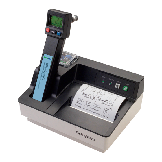
Introduction and technical overview Welch Allyn MicroTymp3 Handle and MicroTymp Printer/Charger Printer/Charger components CHARGE FEED button indicator PRINT button POWER Tip box indicator Charging well for MicroTymp 2 or 3 IEC power cord receptacle Printer/Charger switches Card holder with 1000-Hz... -
Page 11: Symbols
Service manual Introduction and technical overview Symbols Documentation symbols Warning Caution (Warnings indicate conditions or practices (Cautions indicate conditions or practices that could lead to illness, injury, or death.) that could damage the equipment or other property) Consult instructions for use Hot surface Operation symbols POWER indicator... - Page 12 Introduction and technical overview Welch Allyn MicroTymp3 Handle and MicroTymp Printer/Charger Certification symbols Meets essential requirements of European Complies with applicable U.S. and Medical Device Directive 93/42/EEC Canadian medical safety standards 0297 74227 Class I equipment, Type BF European regulatory manager...
-
Page 13: General Warnings
WARNING Explosion risk. Do not use Handle or Printer/Charger near flammable anesthetics. WARNING Electric shock hazard. Do not attempt to disassemble the Printer/ Charger. Refer all servicing to Welch Allyn or a Welch Allyn authorized service representative. WARNING Electric shock hazard. Use the USB connector only to connect to devices complying with IEC 60601-1 or other IEC standards as appropriate to the device. -
Page 14: General Notes
The Printer/Charger (#7117x) will charge and print data from the MicroTymp2 or MicroTymp3 Handle. However, the original Printer/Charger (#7113x) will neither charge nor print data from the MicroTymp3 Handle. Please complete and return the warranty registration. It validates the warranty and allows Welch Allyn to communicate calibration notices and software changes. -
Page 15: Testing And Verification
Testing and verification Tools • Pressure applicator source with range of -400 to +300 daPa with 1 daPa resolution • Variable voltage (0-10 VDC) output power supply with at least 500 mA capacity • Test cavity set, part number T20015974. See picture below for sizes. •... - Page 16 Testing and verification Welch Allyn MicroTymp3 Handle and MicroTymp Printer/Charger B&K sound level meter model 2250 1/2-inch microphone model 4192 and 2 cc coupler model 4946 Off-the-shelf tools Barometer...
-
Page 17: Bench Test And Calibration Check - Handle
Service manual Testing and verification Bench test and calibration check - Handle Purpose of test To test for and detect problems in the following portions of the Handle: 1. Leak and vent rate 2. Noise (226 and 1000 Hz) and sweep rate test 3. -
Page 18: Bench Test Procedures
Testing and verification Welch Allyn MicroTymp3 Handle and MicroTymp Printer/Charger 3. Select the choices as shown in the picture below: 1 for start, 1 for number of connections, and 2 for USB. Note Wait approximately five to ten seconds to allow the "Sample Client" program to recognize the connection. - Page 19 Service manual Testing and verification click will be heard indicating the valve has been latched closed. Unit can now be tested for leaks. 2. Connect pressure box to the probe tip of the Handle. Throw select switch on pressure box to positive position and pressure/vent switch to pressure position. 3.
- Page 20 Testing and verification Welch Allyn MicroTymp3 Handle and MicroTymp Printer/Charger 1000 Hz Typmanogram Volume tested cavity Good tympanogram (226 Hz) Unacceptable tympanogram (226 Hz) Test 3 - Button test for 226 Hz function only 1. Place a 0.5 cc cavity onto the probe tip. Make sure cavity fits properly. The rubber tip from the cavity should not be pulling away from the white tip ejector.
-
Page 21: Final Tester Setup
Service manual Testing and verification Properly applied test cavity No gap shown Unit is now ready for final test on the ATE. All units must be tested on the ATE before shipment to the customer. Note Final Tester Setup Before a unit can be tested on the final tester, the B&K meter must be calibrated at the beginning of each shift. - Page 22 Testing and verification Welch Allyn MicroTymp3 Handle and MicroTymp Printer/Charger 5. Remove the 2cc coupler from the ATE Microphone. Rotate the lock ring on the 2cc coupler counterclockwise to unlock the mechanism. 6. Place the ATE Microphone onto the calibration sound box.
- Page 23 Service manual Testing and verification 9. After the ATE screen displays "Calibration is Complete", rotate the lock ring on the 2cc coupler counterclockwise to unlock the mechanism. Re-insert the B&K microphone into the coupler and ensure that the microphone is fully seated before rotating the lock ring clockwise to lock as shown below.
- Page 24 Testing and verification Welch Allyn MicroTymp3 Handle and MicroTymp Printer/Charger Before testing each new unit, make sure the microphone is pushed all the way into the 2 cc coupler and that the coupler is locked. Once the ATE instructs you to put on the 0.2 cc cavity, you must use the tip ejector on the unit to disengage the microphone with the 2 cc coupler from the unit.
- Page 25 Service manual Testing and verification 4. Place Unit Under Test (UUT) into the ATE Nest. Use the touch screen of the ATE (or the mouse) to begin the test. Follow the ATE Tester direction on the screen. FINAL TESTER Equipment- 20015994 workstation Method- Automated verification and calibration of units Acceptance Criteria- Unit passes all final tests Record- Mark the appropriate PASS or FAIL check box for final...
-
Page 26: Testing Performed By The Ate
Testing and verification Welch Allyn MicroTymp3 Handle and MicroTymp Printer/Charger Testing Performed by the ATE For reference only - actual numbers may change Each Handle that is tested by the ATE receives the following tests: 1. Preliminary Current Check: 20 to 400 ma. -
Page 27: Bench Test For The Printer/Charger
Service manual Testing and verification 25. Admittance Accuracy: checked with 0.5, 1.5, and 2.4 cc cavities. Accuracy needs to be within +/- 0.1 mmho for 226 Hz and +/- 0.4 mmho for 1000 Hz or +/- 5%, whichever is greater. 26. -
Page 28: Proper Operation Of Print Head
Testing and verification Welch Allyn MicroTymp3 Handle and MicroTymp Printer/Charger 5. Power up unit. Power light should blink in a pattern of one on, one off. 6. Install paper roll by feeding under gray rubber printer roll and pressing the feed button. - Page 29 Service manual Testing and verification 2. Make sure there are no gaps in the grid printout and that all lines of date are full with no lines missing through the lettering. 3. Insert Handle into Printer/Charger well with the LCD screen facing forward. The charge light should light.
-
Page 30: Agency Tests
Testing and verification Welch Allyn MicroTymp3 Handle and MicroTymp Printer/Charger 5. On the switch pack on under side of printer, put switch 2 to ON position. Press the print button. Notice the printout. There is no adult/child data. Printout with Switch 2 in ON position 6. -
Page 31: Grounding Continuity Test
Service manual Testing and verification Breakdown will normally be indicated by tripping of a suitable overload protector in the test equipment, but an abrupt decrease or retarded advance of the voltmeter reading could also be indicative of insulation failure. REF: UL544 par. 31.3. A breakdown is also considered to have occurred if after the test the equipment does not comply with risk current test even though there is no arcing, tracking, or other evidence of a breakdown. - Page 32 Testing and verification Welch Allyn MicroTymp3 Handle and MicroTymp Printer/Charger...
-
Page 33: Troubleshooting Guide
Troubleshooting guide Handle Problem Cause Corrective Action No Tone Check solder connections on speaker/ Reflow solder connection microphone flex Make sure speaker/microphone is Reseat speaker/microphone as needed properly seated in boot and on SS tube Check for a clogged SS tube in the Clean tube as necessary front housing Defective speaker/microphone... -
Page 34: Printer/Charger
Troubleshooting guide Welch Allyn MicroTymp3 Handle and MicroTymp Printer/Charger Problem Cause Corrective Action Unit fails current drain test on ATE Pump not finding home position Replace pump Defective PS or MCU board Replace appropriate PC board LCD frozen, unresponsive Microcomputer MCU board has locked... -
Page 35: Noise Troubleshooting Procedure
Service manual Troubleshooting guide Noise troubleshooting procedure The purpose to these instructions is to give a general procedure in fixing a noisy Handle when the cause is not the microphone (second pixel on tympanogram is acceptable). 1. Verify the problem by testing the unit manually with 0.2 cc, 1.0 cc, 2.0 cc, and 2.4 cc cavities. -
Page 36: Leak Troubleshooting Procedure
Troubleshooting guide Welch Allyn MicroTymp3 Handle and MicroTymp Printer/Charger Leak troubleshooting procedure The purpose of this procedure is to isolate a leak in the pneumatic assembly of the Handle so that an accurate diagnosis and repair can be performed. For this procedure a Hemostat tool is required. -
Page 37: Error And Service Code Tables With Troubleshooting Procedure
Service manual Troubleshooting guide Error and service code tables with troubleshooting procedure This procedure shows the error codes, their probable causes and solutions and the method of logging of such codes. Error codes Code Description Probable cause CHECKSUM_ERROR MCU problem THREADX_ERROR MCU problem AUDIO_ERROR... - Page 38 Troubleshooting guide Welch Allyn MicroTymp3 Handle and MicroTymp Printer/Charger If no errors are to be logged, the last two numbers on the error log in this file will be 00 00. This is called a ‘clean’ error log. See example below for explanation.
-
Page 39: Service Codes
Service manual Troubleshooting guide Service codes Service codes are those messages that display on the LCD of the Handle. They indicate the condition of the unit. The available service codes are listed in the ‘Display’ column in the table on the following page. With the exception of the codes ‘NEEDS SVC’ and ‘NEEDS CAL,’... - Page 40 Troubleshooting guide Welch Allyn MicroTymp3 Handle and MicroTymp Printer/Charger All other service codes can be cleared by powering down/powering up. These are the SYS CHK, the SYS CHK0, and the SYS CHK1. These codes indicate that an abnormal condition has occurred in the unit. If powering down/powering up removes the code, the unit is operable.
-
Page 41: Disassembly And Reassembly
Disassembly and reassembly Handle Caution ESD protection must be worn at all times while performing any assembly or disassembly of either the Handle or Printer/Charger. Failure to observe this can cause premature component failure in the field even though such failure may not be evident at the time of the violation. Oftentimes weakened components will operate, even as normal, for a period of time before exhibiting failing characteristics. - Page 42 Disassembly and reassembly Welch Allyn MicroTymp3 Handle and MicroTymp Printer/Charger 2. Remove Welch Allyn logo on front housing and remove the two screws that hold the front housing down. Gently rock housing side to side while lifting. Break glue bond that exists between the side tabs and the housing.
- Page 43 Service manual Disassembly and reassembly Speaker tube Transducertube Microphone tube Microphone tube Removal/replacement of the front housing parts: speaker, microphone, and transducer 1. With the front housing removed, select the component that is to be replaced. If a stable vice is unavailable, unsolder/solder the component while in the front housing assembly for stability purposes.
- Page 44 Disassembly and reassembly Welch Allyn MicroTymp3 Handle and MicroTymp Printer/Charger 2. Remove flex cable from connector on LCD board. Remove flex cable from connectors on the keypad and power boards. These are opposite ends of the same flex cable. 3. Gently pull long transducer silicone tube through the pump frame. Pull from the ballast side of the pump.
- Page 45 Service manual Disassembly and reassembly O-ring drive belt To replace the drive belt, remove pulley retainer. Remove belt from white pulley and motor. Replace with new belt. To avoid getting skin oils on the belt, use tweezers. Pulley retainer Pump pulley With pulley retainer removed, remove drive belt and unscrew pulley from pump.
-
Page 46: Removal/Replacement Of The Lcd And Keypad Board Assemblies
Disassembly and reassembly Welch Allyn MicroTymp3 Handle and MicroTymp Printer/Charger Optical interrupter With the pump assembly in hand, unsolder the four flex cable connections from the optical interrupter. Remove the two Philips head screws on side of pump opposite the motor. -
Page 47: Removal/Replacement Of The Power Pcba
Service manual Disassembly and reassembly Removal/replacement of the power PCBA 1. Remove pump/motor assembly by following steps 1 through 4 on page 2. With a small size Philips screwdriver, remove the four screws located at each corner of the power board. Note the different lengths of the screws between the two in the rear and two in the front of the PC board. -
Page 48: Removal/Replacement Of The Mcu Pcba
Disassembly and reassembly Welch Allyn MicroTymp3 Handle and MicroTymp Printer/Charger Removal/replacement of the MCU PCBA 1. With the power board removed, use a 4-mm or 5/32-inch driver to remove the four standoffs that are holding the MCU board in the housing. Try to use a driver with thin walls because of the proximity of the standoffs to the housing sides. -
Page 49: Replacement Of Lithium Coin Battery
Service manual Disassembly and reassembly Replacement of Lithium coin battery 1. Remove MCU board from housing. 2. Slide coin battery straight out. 3. Slide new coin battery straight in. 4. Push in until whole battery is inside edge of circuit board. Proper placement of ESD shields in the back housing See pictures below to observe correct placement of ESD shields in the Handle. -
Page 50: Printer/Charger
Disassembly and reassembly Welch Allyn MicroTymp3 Handle and MicroTymp Printer/Charger Printer/Charger Caution ESD protection must be worn at all times while performing any assembly or disassembly of either the Handle or Printer/Charger. Failure to observe this can cause premature component failure in the field even though such failure may not be evident at the time of the violation. -
Page 51: Removal/Replacement Of The Main Pc Board And Print Head Assemblies
Service manual Disassembly and reassembly Removal/replacement of the main PC board and print head assemblies 1. Remove top panel assembly. 2. Using a ¼-inch driver socket unscrew the two nuts holding the main PC board to the bottom housing. 3. Lift the main PC board/print head assembly out of the bottom housing. 4. -
Page 52: Removal/Replacement Of The Contact Housing And Ir Flex Assemblies
Disassembly and reassembly Welch Allyn MicroTymp3 Handle and MicroTymp Printer/Charger Removal/replacement of the contact housing and IR flex assemblies 1. Remove top panel. 2. With top panel in hand, grab the housing assembly on the IR PC board, push in, then pull down. -
Page 53: Removal/Replacement Of The Printer Keyboard/Leds Assembly
Service manual Disassembly and reassembly Removal/replacement of the printer keyboard/LEDs assembly 1. Remove top panel assembly. 2. With a sharp straightedge, such as a flat blade screwdriver, gently pry old assembly loose from the top panel assembly. 3. Carefully lift out through opening in top panel. 4. -
Page 54: Removal/Replacement Of Old Main Pc Board And Print Head
Disassembly and reassembly Welch Allyn MicroTymp3 Handle and MicroTymp Printer/Charger 5. Reassemble in the reverse order of disassembly. Recommended torque specification for the screws is 2.5 in./lbs. RFI filter Removal/replacement of old main PC board and print head Units manufactured before June 2000 have an older model print head and main PC board. -
Page 55: A - Repair Parts
Repair parts See Appendix C for accessory part numbers Note Handle 236045 MICROPHONE 236051 SCREW 2-32 .500 FLAT82 PHILLIPS 236081 SCREW 2-56 .375 FLAT82 PHILLIPS 236094 TRAN,NPN,3904,SOT-23,T&R 236095 TRAN,PNP,3906,SOT-23,T&R 236144 REPAIR WARNING LABEL 236197 CALIBRATION CERTIFICATE 236254 CONNECTOR 236259 FIBER STRIP 236382 PRESSURE TRANSDUCER, SILICON, 1PSI, TH 236387... - Page 56 Repair parts Welch Allyn MicroTymp3 Handle and MicroTymp Printer/Charger Handle 713514 FLAT FERRITE FOR FLEX CIRCUITS 713527 ESD SHIELD 713926 TEE CONNECTOR, 1/16 ID TUBING, NYLON 713935 SILICONE TUBE, .031ID X 2.00 LG 713936 SILICONE TUBE, .062ID X .40 LG...
- Page 57 Service manual Repair parts Handle 236425-1 TAPE, ESD, .75" X .10" 236427-501 BALLAST ASSY M11120 6 X 12 POLY BAG 2MIL M11385 DISPOSABLE DISPENS1NG TIP 900264 FOAM INSERT SET MT Printer/Charger 711749 PRINTER IR PCB/FLEX 711755 BUMPER, CHARGING WELL 711774 SHIELD, HEAT SINK 711786 FLAT FLEX CABLE,KEYPAD,1MM X 6...
- Page 58 Repair parts Welch Allyn MicroTymp3 Handle and MicroTymp Printer/Charger MT Printer/Charger 761195-501 PRINTER COVER & CUTTER ASSY CURRENT 761196-1 WELL, PRINTER 761199-501 ASSY,PRINTER WELL & PCB 761202-501 ASSY, PCB, PRNTR/CHGR M11120 6 X 12 POLY BAG 2MIL M11385 DISPOSABLE DISPENS1NG TIP...
-
Page 59: B - Cleaning
Cleaning Clean the handle Clean the Handle by wiping it with a cloth that has been lightly dampened with 70% Isopropyl alcohol. Ensure that liquid does not seep into the instrument, especially in the probe area. Clean the printer/charger Clean the Printer/Charger by wiping it with a cloth that has been lightly dampened with 70% Isopropyl alcohol. - Page 60 Cleaning Welch Allyn MicroTymp3 Handle and MicroTymp Printer/Charger...
-
Page 61: C - Replacement Parts And Accessories
Replacement parts and accessories Items are not drawn to scale. Note Battery #72910 3.7 V Lithium-ion Screw for Battery Cover #236081 Screw Driver for Battery Cover #236200-2 MicroTest Cavity 2.0 cc 0.5 cc #711772-501 MicroT est CA VITY Probe Tips - Four of the selected size in a bag #24621 #24622... - Page 62 Replacement parts and accessories Welch Allyn MicroTymp3 Handle and MicroTymp Printer/Charger 1000-Hz Screening Results Cards - Quantity 100: four packs of 25 #55270 Replacement Power Cords (order by plug type) #761076-0 #761076-2 #761076-4 #761076-6 120 V 230 V 230 V...
- Page 64 406695 Material No. 718441 Ver A...
Need help?
Do you have a question about the MicroTymp 3 Handle and is the answer not in the manual?
Questions and answers