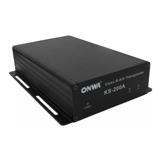
Summary of Contents for Onwa KS-200A
- Page 1 KS-200A/B Ë µ Ã ÷ Ê é KS-200A/B Ë µ Ã ÷ Ê é OPERATOR`S MANUAL AIS Class B Transponder KS-200A AIS Receiver KS-200B...
- Page 3 Continued use of the equipment can Connection of an incorrect power cause fire or electrical shock.Contact a ONWA agent for service. supply can cause fire or equipment damage. Use the proper fuse. Use the proper fuse.
-
Page 4: Table Of Contents
Table of Contents FOREWORD SYSTEM CONFIGURATION KS-200A BASIC OPERATION KS-200B BASIC OPERATION INSTALLATION 1. Scope of Delivery 2. Power Connection 3. Antenna Installation 4. Installation of GPS Antenna 5. Installation of VHF Antenna 6. Connect to other navigational equipment 7. Connection to PC 8. -
Page 5: Foreword
FOREWORD How AIS Works 1. What is AIS AIS stands for Automatic Identification System. AIS increases navigational safety and collision avoidance by transmitting vessel identification, helping to reduce the difficulty of identifying ships when not in sight (e.g. at night, in radar blind arcs or shadows or at distance) by broadcasting navigational intentions to other vessels by providing ID, position, course, speed and other ship data with all other nearby ships and land based stations. - Page 6 2.1 Class A Class A units are a mandatory fit under the safety of life at sea (SOLAS) convention to vessels above 300 gross tons or which carry more than 11 passengers in International waters. Many other commercial vessels and some leisure craft also may be fitted Class A units.
- Page 7 2005. This document is obligatory for class B. Class B units are designed for fitting in vessels which do not fall into the mandatory Class A fit category. The KS-200A is a Class B AIS unit Reporting intervals are: Dynamic ship data: boats at <...
- Page 8 Electrical Interface: -RS232 38.4kbaud bi-directional Environmental: -IEC 60945 (Cat C) -Operating Temperature: -25 to +55 KS-200A: GPS Receiver (AIS Internal) -IEC 61108-1 compliant Connectors -VHF Antenna connector PL259 female -GPS Antenna connector BNC female -RS232 data connector Female 9 Way D-type...
- Page 9 KS200B: Connectors -VHF Antenna connector PL259 female -RS232 data connector Female 9 Way D-type VHF Receiver -Receiver x 2 (one time shared between AIS/DSC) -Frequency: 156.025 to 162.025 MHz in 25KHz steps -Channel bandwidth: 25KHz -RX sensitivity <-107dBm at 20% packet error rate Compliant with the following standards: -IEC62287-1 (IEC standard, Class B shipbourne equipment) -IEC60945 Edn 4.0 (IEC standard, environmental requirements)
-
Page 10: System Configuration
KS-200A SYSTEM CONFIGURATION VHF Antenna GPS Antenna DC 10V 35V... - Page 11 KS-200B SYSTEM CONFIGURATION VHF Antenna DC 10V 35V...
-
Page 12: Ks-200A Basic Operation
KS-200A BASIC OPERATION Turning Power ON/OFF Turning Power ON Press [ON/OFF] to ON direction to turn on the power. Turning Power OFF Press [ON/FF] to OFF direction to turn off the power. Notice : If the equipment remain long time no use, it is better to turn off the Main Power Source switch. -
Page 13: Ks-200B Basic Operation
KS-200B BASIC OPERATION Turning Power ON/OFF Turning Power ON Press [ON/OFF] to ON direction to turn on the power. Turning Power OFF Press [ON/FF] to OFF direction to turn off the power. Notice : If the equipment remain long time no use, it is better to turn off the Main Power Source switch. -
Page 14: Installation
Remark Main unit KS-200A/B Power Cable KS2-PWR Data Cable KS2-data1 Data Cable KS2-data2 Only for KS-200A KS2-CD Operator's Manual KS2-manual Only for KS-200A GPS Antenna KA-07 2.Power Connection Connect power cable to 12VDC (10~ 35VDC) supply, white wire to supply positive +ve and black wire to supply negative -ve. -
Page 15: Installation Of Gps Antenna
Installation of GPS Antenna The GPS antenna is mounted in an elevated position and free of shadow effect from the ship's superstructure. The GPS antenna has a free view through 360 degrees with a vertical angle of 5 to 90 degrees above the horizon. As the received GPS signal is very sensitive to noise and interference generated by other onboard transmitters, ensure that the GNSS antenna is placed as far away as possible from radar, Inmarsat and Iridium... -
Page 16: Installation Of Vhf Antenna
INSTALLTION WITH A PLPE (CUSTOMER`S CARE) Antenna Antenna Cable Pipe Connector 5. Installation of VHF Antenna For the VHF antenna there is a VHF female bulkhead connector used, that mounts to the back of the case. The VHF antenna employed for AIS use: Must be a dedicated antenna, i.e. -
Page 17: Connect To Other Navigational Equipment
6. Connect to other navigational equipment You can use the delivered cable (KS2-data1) to connect the AIS to other navigational equipments such as plotter, radar etc. Please connect the DB9 connector of KS2-data1 cable to the DB9 socket of KS200A/B. Connect the other end of KS2-data1 cable to external navigational equipments according to the following diagram : DB9 pin no. -
Page 18: Connection To Pc
7. Connect to PC You could use delivered cable (KS2-data2) to connect AIS data to PC as following diagram: 9-pin serial port of the computer KS-200A/B -Receive data 2-Orange-TX Data -Send data 3- Green-RX Data -GND 5- Black-GND 1.5M DB9 (Male) DB9 (Female) 8. -
Page 19: Maintenance And Troubleshooting
MAINTENANCE and TROUBLESHOOTING 1.Maintenance Unauthorized opening of the KS200A/B system will invalidate the warranty. Avoid using chemical solvents to clean the KS200A/B as some solvents can damage the case material. To clean, wipe down with a damp cloth. The KS200A/B contains no user serviceable parts. Contact your Service Agent for repair or for replacing. -
Page 20: Connection Diagram
CONNECTION DIAGRAM KS200A Connection Diagram VHF antenna Power Switch GPS Antenna S/NO.200A1001 Data cable Power Cable KS200B Connection Diagram VHF antenna Power Switch S/NO.200A1001 Data cable Power Cable... -
Page 21: Dimensions
DIMENSION 155.8 126.6 14.6...


Need help?
Do you have a question about the KS-200A and is the answer not in the manual?
Questions and answers