Table of Contents
Advertisement
Quick Links
1
SERVICE MANUAL
Level 1&2
Transceiver characteristics
Band:
RM-429: Quad-band GSM 850/900/1800/1900
Display:
2,0" 240 x 320 pixel, 262 k TFT colour primary
display
1,36" 128 x 160 pixel, 262 k TFT colour secondary
display
Camera:
1.3 Mpix with 6x digital zoom
Operating System:
Series 40 3
Connections:
Micro USB, Bluetooth 2.0 + EDR, 2,5 mm AV
connector
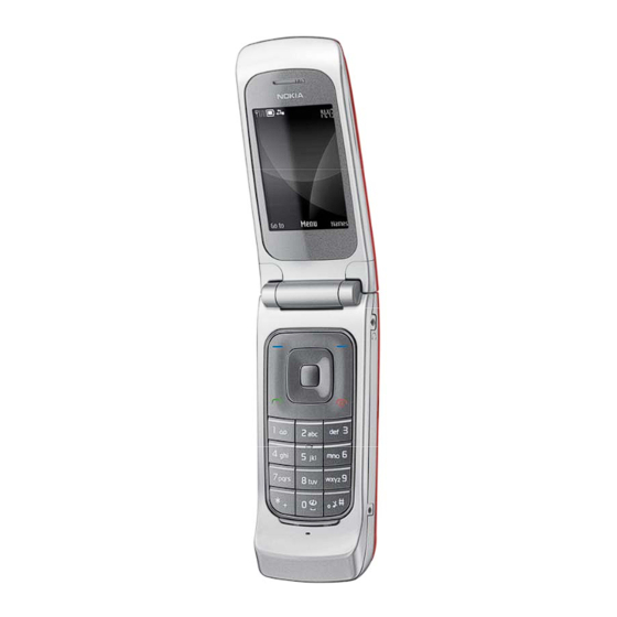
Transceiver with BL-5C battery pack
Talk time
Up to 4 h 38
min
Confidential
Copyright @ 2008 NOKIA. All rights reserved
Service Manual Level 1&2
edition
rd
Standby
Up to 457
hours
3610a RM-429
Note
Depends on
network
parameters
and phone
settings
ISSUE 2
Advertisement
Table of Contents

Subscribe to Our Youtube Channel
Related Manuals for Nokia 3610A


Summary of Contents for Nokia 3610A
- Page 1 Micro USB, Bluetooth 2.0 + EDR, 2,5 mm AV connector Transceiver with BL-5C battery pack Talk time Standby Note Up to 4 h 38 Up to 457 Depends on hours network parameters and phone settings ISSUE 2 Confidential Copyright @ 2008 NOKIA. All rights reserved...
-
Page 2: Table Of Contents
Exploded view ..........................9 Solder components........................10 Service devices ..........................11 SW-update..........................13 Disassembly instruction ......................14 11.1 Upper block disassembly ..................... 14 11.2 Lower block disassembly ..................... 18 Assembly hints........................21 ISSUE 2 Confidential Copyright @ 2008 NOKIA. All rights reserved... -
Page 3: Change History
Solder components updated. The purpose of this document is to help NOKIA service levels 1 and 2 workshop technicians to carry out service to NOKIA products. This Service Manual is to be used only by authorized NOKIA service suppliers, and the content of it is confidential. Please note that NOKIA provides also other guidance documents (e.g. -
Page 4: Copyright
Nokia operates a policy of continuous development. Nokia reserves the right to make changes and improvements to any of the products described in this document without prior notice. Under no circumstances shall Nokia be responsible for any loss of data or income or any special, incidental, consequential or indirect damages howsoever caused. -
Page 5: Warnings And Cautions
3. Use only approved components as specified in the parts list. 4. Ensure all components, modules screws and insulators are correctly re–fitted after servicing and alignment. 5. Ensure all cables and wires are repositioned correctly ISSUE 2 Confidential Copyright @ 2008 NOKIA. All rights reserved... -
Page 6: Esd Protection
3610a RM-429 Service Manual Level 1&2 4. ESD PROTECTION Nokia requires that service points have sufficient ESD protection (against static electricity) when servicing the phone. Any product of which the covers are removed must be handled with ESD protection. The SIM card can be replaced without ESD protection if the product is otherwise ready for use. -
Page 7: Care And Maintenance
Use only the supplied or an approved replacement antenna. Unauthorised antennas, modifications or attachments could damage the phone and may violate regulations governing radio devices. All of the above suggestions apply equally to the product, battery, charger or any accessory. ISSUE 2 Confidential Copyright @ 2008 NOKIA. All rights reserved... -
Page 8: Battery Information
Batteries’ performance is particularly limited in temperatures well below freezing. Do not dispose batteries in a fire! Dispose of batteries according to local regulations (e.g. recycling). Do not dispose as household waste. ISSUE 2 Confidential Copyright @ 2008 NOKIA. All rights reserved... -
Page 9: Exploded View
3610a RM-429 Service Manual Level 1&2 7. EXPLODED VIEW See corresponding ITEM/CIRCUIT REF in the Spare Parts Service Bulletins on NOL. ISSUE 2 Confidential Copyright @ 2008 NOKIA. All rights reserved... -
Page 10: Solder Components
3610a RM-429 Service Manual Level 1&2 8. SOLDER COMPONENTS 3610a RM-429 Components overview Solder components only for Level 2 ISSUE 2 Confidential Copyright @ 2008 NOKIA. All rights reserved... -
Page 11: Service Devices
Service Cable to connect the PC with the mini USB connector. RJ-230 Universal Soldering Jig Internal Battery BL-5C Inserted under the back cover, this Li-Ion battery provides power in a lightweight package. ISSUE 2 Confidential Copyright @ 2008 NOKIA. All rights reserved... - Page 12 For more information, refer to the Service Bulletin (SB-011) on Nokia Online. Supplier of manufacturer contacts for tool re-order can be found in “Recommended service equipment” document on Nokia Online. ISSUE 2 Confidential Copyright @ 2008 NOKIA. All rights reserved...
-
Page 13: Sw-Update
To use the FLS-5 Flash Dongle, you have to follow the user guide inside the sales package. Please check always for the latest version of flash software, which is available on Nokia Online. Note: This illustration shows a generic transceiver and battery. -
Page 14: Disassembly Instruction
4) Use TORX 4 screwdriver to remove 2 screws. Do clockwise to release SCREW CAPS. not use them again. 5) Insert SRT-6 tool and slide along edges to 6) Remove A-Cover. release tabs on both sides. ISSUE 2 Confidential Copyright @ 2008 NOKIA. All rights reserved... - Page 15 10) Lift up and remove IHF SPEAKER. 11) Use T0RX 4 screwdriver to unscrew AUSTRALIA 12) Use tweezers to remove AUSTRALIA CONNECTOR BRACKET screw. Do not use screw CONNECTOR BRACKET. again. ISSUE 2 Confidential Copyright @ 2008 NOKIA. All rights reserved...
- Page 16 16) Use SS-93 tool to release Board to Board small LCD. Connector. 17) Use SS-93 tool to release Connector of the 18) Carefully insert small flat head screwdriver large LCD. and release tabs of DISPLAY SUPPORT. ISSUE 2 Confidential Copyright @ 2008 NOKIA. All rights reserved...
- Page 17 21) Remove small LCD. 22) Lift up and remove UPPER UI ASSEMBLY WITH FLEX ASSEMBLIES. 23) Use SS-88 tool to remove CAMERA MODULE. 24) Use SS-93 tool to release tabs from LCD. ISSUE 2 Confidential Copyright @ 2008 NOKIA. All rights reserved...
-
Page 18: Lower Block Disassembly
11.2 Lower block disassembly 29) Remove 4 Screws with TORX 6 Screwdriver in 30) Insert SRT-6 Tool to slide along edges to the order as shown. release Tabs on both sides. ISSUE 2 Confidential Copyright @ 2008 NOKIA. All rights reserved... - Page 19 32) Use SS-93 Tool to remove ANTENNA. 33) Remove DC-JACK. 34) Use SS-93 Tool to release Board to Board Connector. 35) Use SS-93 Tool to release Tabs from D-COVER. 36) Lift up and remove PWB. ISSUE 2 Confidential Copyright @ 2008 NOKIA. All rights reserved...
- Page 20 3610a RM-429 Service Manual Level 1&2 37) Remove HARDCAP KEYMAT. 38) Remove DAMPER with Tweezers. 39) Use Dental Pick to release DOMESHEET. 40) Peel off DOMESHEET. ISSUE 2 Confidential Copyright @ 2008 NOKIA. All rights reserved...
-
Page 21: Assembly Hints
2) Tighten the screws to the torque of 14 Ncm +/-1 in the order shown. in the order shown. 3) Tighten the screws to the torque of 10 Nm in the order shown. ISSUE 2 Confidential Copyright @ 2008 NOKIA. All rights reserved...
Need help?
Do you have a question about the 3610A and is the answer not in the manual?
Questions and answers