Sign In
Upload
Download
Table of Contents
Contents
Add to my manuals
Delete from my manuals
Share
URL of this page:
HTML Link:
Bookmark this page
Add
Manual will be automatically added to "My Manuals"
Print this page
×
Bookmark added
×
Added to my manuals
Manuals
Brands
LG Manuals
Dryer
RC9011 Series
Service manual
LG RC9011 Series Service Manual
Condensing dryer
Hide thumbs
1
2
3
Table Of Contents
4
5
6
7
8
9
10
11
12
13
14
15
16
17
18
19
20
21
22
23
24
25
26
27
28
29
30
31
32
33
34
35
36
37
page
of
37
Go
/
37
Contents
Table of Contents
Troubleshooting
Bookmarks
Table of Contents
Table of Contents
Specifications
Features and Look
Part Identification
Program Cycle
Cycle Selection Table
Installation Instructions
Condensate Drain
Maintenance Instructions
Component Testing Tips
Control Lay-Out
Wiring Diagram
Troubleshooting
Error Mode
Diagostic Test
Diassemble Instructions
Exploded View
Advertisement
Quick Links
1
Part Identification
2
Condensate Drain
3
Maintenance Instructions
4
Troubleshooting
5
Diagostic Test
6
Diassemble Instructions
7
Exploded View
Download this manual
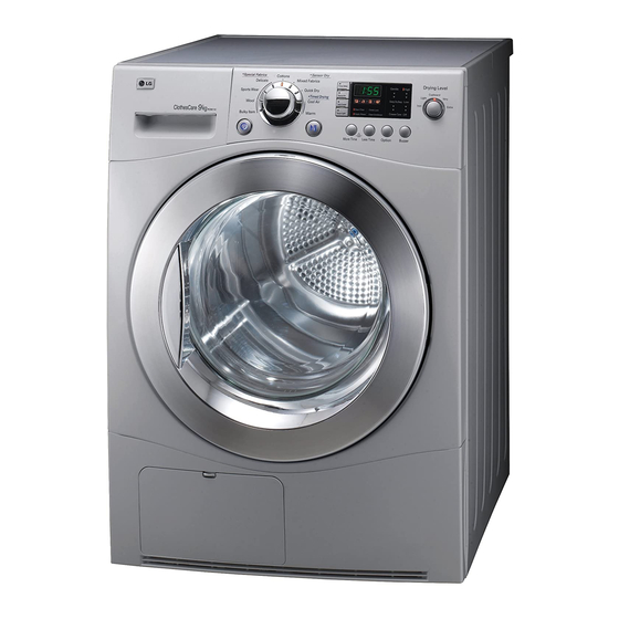
CONDENSING DRYER
SERVICE MANUAL
CAUTION
READ THIS MANUAL CAREFULLY TO DIAGNOSE TROUBLE
CORRECTLY BEFORE OFFERING SERVICE.
MODEL : RC9011** / RC8011** Series
Table of
Contents
Previous
Page
Next
Page
1
2
3
4
5
Advertisement
Table of Contents
Need help?
Do you have a question about the RC9011 Series and is the answer not in the manual?
Ask a question
Questions and answers
Related Manuals for LG RC9011 Series
Dryer LG RC9011A Use And Care Manual
9kg dryer (24 pages)
Dryer LG RC9011B Use And Care Manual
Condensing dryer (24 pages)
Dryer LG RC9011C Use And Care Manual
9kg dryer (24 pages)
Dryer LG TD-C9011A Owner's Manual
(64 pages)
Dryer LG RC9011G2 Owner's Manual
(28 pages)
Dryer LG RC9041E2 Owner's Manual
(28 pages)
Dryer LG RC9042AQ3Z Owner's Manual
Lg heat pump dryer (32 pages)
Dryer LG RC9041A Owner's Manual
(28 pages)
Dryer LG RC9055*P*Z Service Manual
Heat pump (56 pages)
Dryer LG RC90V9AV2W Owner's Manual
(48 pages)
Dryer LG RC90V9JV2W Owner's Manual
(48 pages)
Dryer LG RC80U2 V Series Owner's Manual
(76 pages)
Dryer LG RC90V9AV3Q Owner's Manual
(39 pages)
Dryer LG RC90V9AV2Q Owner's Manual
(39 pages)
Dryer LG RC9055 P Z Series Service Manual
Heat pump dryer (47 pages)
Dryer LG RC9055 P F Series Owner's Manual
(36 pages)
This manual is also suitable for:
Rc8011 series
Table of Contents
Save PDF
Print
Rename the bookmark
Delete bookmark?
Delete from my manuals?
Login
Sign In
OR
Sign in with Facebook
Sign in with Google
Upload manual
Upload from disk
Upload from URL


Need help?
Do you have a question about the RC9011 Series and is the answer not in the manual?
Questions and answers