
Related Manuals for Aristel DV-22


Summary of Contents for Aristel DV-22
-
Page 1: Installation Manual
System Installation Manual Digital Key Telephone System Aristel Digital Key Telephone System DV-22 Installation Manual Aristel Networks Pty Ltd... -
Page 2: Table Of Contents
3.2 E ..................11 NVIRONMENT EQUIREMENT 3.3 C ....................11 ABLE EQUIREMENT 3.4 N ........................11 OTICE 4. DV-22 PCB AND CABINET LAYOUT ..................13 4.1 DV-22 SYSTEM DIAGRAM ..................13 4.2 D4PWUA ............. 14 ANGE OWER DAPTOR 4.3 D4MBUB(C) (M ................. 15... - Page 3 System Installation Manual Digital Key Telephone System 5. DV-22 PCB AND CABINET LAYOUT ..................22 5.1 P ....................22 OWER NSTALLATION 5.2 CO L ....................23 NSTALLATION 5.3 S ....................24 TATION NSTALLATION 5.4 D ..................25 HONE NSTALLATION 5.5 S ....................
-
Page 4: Introduction
INTRODUCTION: Congratulations on your selection of the ARISTEL DV-22 SOHO System! ARISTEL DV-22 is a state-of-the-art communication system that offers you unique features, flexibility and superb service in your office or in your home. ARISTEL DV-22 system’s digital technology extends well beyond handling just conventional phone calls. -
Page 5: System Summary
Key phone operation security:Error operation recovery protection program. Extension Error Action Protection:Extension error action protection mode 1.3 Safety Conformity FCC、CE、AUSTEL、TAS、SIRIM Internal/External Lines Short Circuit Protection Power Mingled Dispatch Restraint Lightning Protection Power Fluid Transformation : AC110 ~ AC240 KEY PAD Endurance:1,000,000 Times Aristel Networks Pty Ltd... -
Page 6: Hardware Configuration
Single Line Telephone 1 / 2 / 4 / 8 Door Phone Connection Relay Interface Sensor Interface Auto Attendant 1 / 2 RS232 for SMDR Speed Dial set 1000 1000 Power Failure Telephone interface Virtual Extensions Aristel Networks Pty Ltd... -
Page 7: Electrical Specifications
310 × 205 × 70 mm System Dimension (mm, W×D×H) 200L × 180W × 75H mm Key Telephone Dimension (mm) Working Temperature 0 C ~ 45 C (32 F ~ 113 Working Humidity 10% ~ 90% relative non-condensing Aristel Networks Pty Ltd... -
Page 8: Key Telephone Specification
8 levels Short-circuited Protection Handsfree Conversation … One-Touch Paging Last outgoing Redial Calculator … Individual Speed Dial 20 sets 20 sets 20 sets 20 sets Different Ringing 9 selections 9 selections 9 selections 9 selections Frequencies Aristel Networks Pty Ltd... -
Page 9: System Model Description
VOICE SERVICE CARD, consisting of 2 Voice Channels (60 seconds) with Fax Detection D4VSCC function D4MFCA MULTI FUNCTION CARD, consisting of (1 Sensor + 1 Relay + 1 Door Phone Port) D4MFCB MULTI FUNCTION CARD, consisting of 1 Door Phone Port D1CIDC FSK/DTMF CLI INTERFACE Aristel Networks Pty Ltd... -
Page 10: System Features List
Illegal Outgoing Prohibit Intercom Busy Reminder Incoming Hunting Incoming Paging Intercom Hunting Internal/External Music Source Internal/External Paging Key Station Short Protection Lightning Protection Message Waiting Name Speed Dialing (Phone Book) One Touch Operation Power Failure Telephone Aristel Networks Pty Ltd... -
Page 11: Station Features List
Call Pick Up Station Name Setting Call Transfer Station Operation Help List Camp On Day/Night Service Indication Digital Volume Control (8 Levels) Do Not Disturb means the optional function. Dual-Color/Tri-Status BLF Indication DSS Console Handsfree Dialing Aristel Networks Pty Ltd... -
Page 12: Equipment Requirement
Install main unit in the center position of the extensions to shorten the distance between main unit and extensions. The power supply must be independent from the others. And keep away from high frequency sources and noise to avoid interference from EMI. Aristel Networks Pty Ltd... - Page 13 Install lightning rod ground wire to ensure stability of system. Use twin wire to avoid noise and interference when the wiring is too long. Keep away from the power cord and interference source. Otherwise, it’s necessary to use segregated wire and install a ground wire. Aristel Networks Pty Ltd...
-
Page 14: Pcb And Cabinet Layout
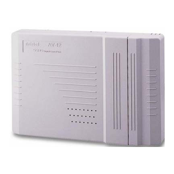
System Installation Manual Digital Key Telephone System 4. DV-22 PCB AND CABINET LAYOUT 4.1 DV-22 SYSTEM DIAGRAM Figure 1: DV-22 Diagram 1. System Dimension:306 x 205 x 70mm 2. System AC Input:110~240VAC 3. External Backup Battery Input : 24VDC Aristel Networks Pty Ltd... -
Page 15: D4Pwua - Full Range Power Adaptor
System Installation Manual Digital Key Telephone System 4.2 D4PWUA – Full Range Power Adaptor Figure 2: DV-22 power adaptor D4PWUA front view 1. AC Input:110~240VAC Full range 2. DC Output:28VDC Aristel Networks Pty Ltd... -
Page 16: D4Mbub(C) (Mother Board Unit)
System Installation Manual Digital Key Telephone System 4.3 D4MBUB(C) (Mother Board Unit) Figure 3: DV-22 Mother board Unit (D4MBUB) System Software EEPROM System Software RAM backup battery Switch System Software RAM backup battery Key phone port connector Trunk port connector... -
Page 17: D4Tkub (Trunk Unit)
System Installation Manual Digital Key Telephone System 4.4 D4TKUB (Trunk Unit) Figure 4: DV-22 CO Trunk Card Unit (D4TKUB) 1. For D4MBUB connection. RJ-12 Connectors for CO Line Connection NOTE:D4TKUB(CO Trunk CARD)consists of 3 CO Lines REFER TO PAGE 23 FOR CONNECTION DETAILS... -
Page 18: D4Dlub(Key Station Card
System Installation Manual Digital Key Telephone System 4.5 D4DLUB(Key Station Card) Figure 5: DV-22 Key Station Card Unit (D4DLUB) 1. For D4MBUB connection. 2. Quick-Connector Module for Key phone connection,(Use 2-wire T/R), including 4 sets of 6 wires RJ-12 Connector. -
Page 19: D4Slcc (Slt Station Card)
System Installation Manual Digital Key Telephone System 4.6 D4SLCC (SLT Station Card) Figure 6: DV-22 SLT Station Card Unit (D4SLCC) 1. For D4MBUB connection. 2. Quick-Connector Module for Single Line phone connection(Use 2-wire T/R), including 2 sets of 6-wire RJ-12 connector. -
Page 20: D4Hyub(Hybrid Station Unit
System Installation Manual Digital Key Telephone System 4.7 D4HYUB(Hybrid Station Unit) Figure 7:DV-22 Hybrid Station Unit 1. For D4MBUB connection. Quick-Connector Module for Key Station Wiring, or Single Line Telephone (Use 2-wire T/R), including 4 sets of 6-wire RJ-12 connector. -
Page 21: D4Vsca (Voice Service Card)
System Installation Manual Digital Key Telephone System 4.8 D4VSCA (Voice Service Card) Figure 8: DV-22 Voice Service Card (D4VSCA/B) 1. For D4MBUB connection. 2. LED:To indicate the channel 1 is working when LED is blinking. 3. LED:To indicate the channel 2 is working when LED is blinking. -
Page 22: D4Mfca/B (Multi Function Card)
System Installation Manual Digital Key Telephone System 4.9 D4MFCA/B (Multi Function Card) Figure 9:DV-22 Multi Function Card (D4MFCA/B) 1. For D4MBUB connection. 2. A-B: Terminal-Block Connector, for the Relay Connection. 3. DOOR: Terminal-Block Connector, for the Door Phone Connection. 4. SEN: Terminal-Block Connector, for the Sensor Connection. -
Page 23: Pcb And Cabinet Layout
System Installation Manual Digital Key Telephone System 5. INSTALLATION AND WIRING POWER INSTALLATION Figure 10:DV-22 Power Installation Aristel Networks Pty Ltd... -
Page 24: Co Line Installation
3 & 4 for Line 1, pins 2 & 5 for Line 2 WARNING: Do not use 4 wire telephone line cord to connect CO lines straight into RJ12 socket – use 2 wire line cord Figure 11: CO line installation Aristel Networks Pty Ltd... -
Page 25: Station Installation
3 & 4 for Line 1, pins 2 & 5 for Line 2 WARNING: Do not use 4 wire telephone line cord to connect phones straight into RJ12 sockets - use 2 wire line cord Figure 12:Station Installation Aristel Networks Pty Ltd... -
Page 26: Door Phone Installation
System Installation Manual Digital Key Telephone System DOOR PHONE CONNECTION Figure 13: Door phone installation Aristel Networks Pty Ltd... -
Page 27: Sensor Installation
System Installation Manual Digital Key Telephone System SENSOR INSTALLATION Figure 14: Sensor installation Aristel Networks Pty Ltd... -
Page 28: Door Switch Connection
System Installation Manual Digital Key Telephone System DOOR SWITCH CONNECTION Connect to Door Switch Power Figure 15: Door switch installation Aristel Networks Pty Ltd... -
Page 29: External Music Installation
System Installation Manual Digital Key Telephone System EXTERNAL MUSIC INSTALLATION Figure 16: External music installation Aristel Networks Pty Ltd... -
Page 30: Virtual Extensions
3-6 Co lines and 8-16 station ports. In addition there are 16 virtual extensions. The Motherboard occupies the lower deck whereas expansion cards are fixed on the upper deck. Programming aspects of DV22 are similar to earlier Aristel systems but with minor changes. Multifunction card has a dedicated position on the upper deck. - Page 31 System Installation Manual Digital Key Telephone System DOC : DV-22 Installation Manual Edition Version: 1.1 Part No.: 72000686 Editor : Date : 12 December 2007 This document contains proprietary information and may not be reproduced in any form without the express written consent of Arista Systems Corporation.
Need help?
Do you have a question about the DV-22 and is the answer not in the manual?
Questions and answers