Table of Contents
Advertisement
Quick Links
Available Models
EM38A: no internal relays.
EM38A-R: 8 relays for simple control.
EM38A-X: 8 relays for complex control.
Technical Specifications
Operation Mode
playback only
Sound File Format
MP3 (ISO 11172-3)
Max. Number of Sound Files
Parallel / Direct Mode: 8
Parallel / Binary Mode: 128
Parallel / Sequential Mode: 8 x 99
Parallel / Round-Robin Mode: 8
Parallel / Script Mode: 999
Serial Port: 999
Memory Card Type
SD/SDHC
Max. Memory Capacity
2 GB for SD (FAT/FAT16)
32 GB for SDHC (FAT32)
Max. Recording Time (w/2GB card)
33 hours (based on 128 kbps bit rate)
Supply Voltage
12 ~ 30 VDC
Typical Standby Current
60 mA
Audio Output
(30V supply, 8 Ohm load, 10% THD+N)
High efficiency class D
Stereo: 15W per channel
Mono: 55W bridge tied load (BTL)
Serial Interface
RS-232 / RS-485
Trigger Inputs
8 inputs, contact closure or 3.3V/5V logic
Physical Dimensions
EM38A
5.3'' x 4'' x 1.35''
EM38A-R & EM38A-X
5.3'' x 6.7'' x 1.35''
EM38A / EM38A-R / EM38A-X User's Manual
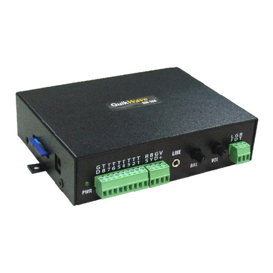
Inputs, Outputs & Controls
Power Light (PWR)
The power light is turned on when power is applied.
Trigger Inputs Terminals: T1 - T8, GD
The trigger inputs terminals are enabled by default, but disabled automatically if the
serial port is enabled. Both dry contact closure and 3.3V/5V logic signal are acceptable.
Trigger inputs may work differently depending on the particular trigger mode described
later. The GD terminal is ground, connected internally to the power ground.
Reset Input Terminal: RS
Connect this input to the ground momentarily to reset the unit. Min. duration is 100 ms.
Busy Output Terminal: BY
This open collector output from an internal transistor can be controlled with more flex-
ibility if the unit runs in the Script mode. In all other modes it is automatically turned on
while playing audio, with a maximum sink current of 200 mA. It can be used to synchro-
nously activate an external relay for switching on a device such as a lamp or a motor.
Power Input Terminals: V+, GD
Use a well regulated DC power supply to obtain the best sound quality. Connect the power
supply's positive output to terminal V+, and the negative output to terminal GD. Alterna-
tively, power can also be supplied via the 2.1mm center positive coaxial jack located on
the left side of the unit.
Line Output (LINE): 1/8" Stereo Phone Jack
This jack provides single ended line output.
Balance Pot (BAL)
This pot adjusts the output balance between the two channels. It should be set at the
middle (center detent) if the unit is configured for BTL (bridge tied load) mono out.
Volume Pot (VOL)
Turn this pot clockwise to increase the output volume. It affects both the speaker and
the line out.
Speaker Output Terminals: LF (left channel), GD, RT (right channel)
See the Speaker Connections section.
Serial Port (DB9 Female)
The default setting is RS-232. To select RS-485, move the internal jumper JP1 to the
"485" setting. The serial port is disabled by default. To enable the serial port, you must
create a configuration file (MODE.TXT) on the flash card as described later. The trigger
inputs are disabled automatically when the serial port is enable.
DC Adaptor Jack
Instead of the power input terminals, power can also be supplied via this 2.1mm center
positive coaxial jack located on the left side of the unit.
Relay Output Terminals (EM38A-R & EM38A-X only)
Three terminals are provided for each relay: NC (Normally Closed), NO (Normally Open)
and Common. The contact is rated at 12A/120VAC or 10A/24VDC.
Typical wiring diagram for push button activation
Page 1 of 8
Advertisement
Table of Contents

Related Manuals for Eletech EM38A

Summary of Contents for Eletech EM38A
-
Page 1: Technical Specifications
EM38A / EM38A-R / EM38A-X User’s Manual Page 1 of 8 Inputs, Outputs & Controls Power Light (PWR) The power light is turned on when power is applied. Trigger Inputs Terminals: T1 - T8, GD The trigger inputs terminals are enabled by default, but disabled automatically if the serial port is enabled. -
Page 2: Speaker Connections
EM38A / EM38A-R / EM38A-X User’s Manual Page 2 of 8 Parallel Trigger Modes Parallel Playback Modes Parallel Trigger Mode defines how the playback is to be triggered Non-interruptible Playback (default) via the trigger inputs. All inputs are internally pulled up and, if left The file is played once per trigger. - Page 3 BN - turn on the Busy output music while no trigger is being executed. For example, Use this command to turn the Busy output on. XNn - turn on relay #n (EM38A-R & EM38A-X only) I000=F123,J000 Example: XN8 turns on relay #8.
-
Page 4: System Configuration File
EM38A / EM38A-R / EM38A-X User’s Manual Page 4 of 8 Relay Control (EM38A-R / EM38A-X only) System Configuration File The relays are controlled differently in different modes: By default, the system works in the following mode without a configu... -
Page 5: Serial Interface
EM38A / EM38A-R / EM38A-X User’s Manual Page 5 of 8 Serial Interface Testing the Serial Port When the serial interface is enabled, all parallel inputs T1 ~ T8 are The serial port can be easily tested by using a Windows utility pro- disabled and all Parallel Modes are no longer available. -
Page 6: Serial Commands
“XFF”. This command can be issued at any time. back command to stop the currrent playback first before starting a new one. Send Binary to Relay (EM38A-R & EM38A-X only) DTE Sends: Xnnn (nnn is a 3-digit number with leading zeros) Stop Playback... -
Page 7: Application Example
- If both buttons are pressed or held down at the same time, button must be released first. button #1 prevails. 6. EM38A-R: Turn on a single, different relay for each sound. 2. Allow interruption during playback. Intended Operation Intended Operation - Turn on relay #1 when playing file #001. - Page 8 EM38A / EM38A-R / EM38A-X User’s Manual Page 8 of 8 Application Example Application Example Automatic Playback on Power-up Using Normally Closed Switches & Sensors 1. Repeat continuously on power-up. Intended Operation Normally closed switches and sensors are often used in security - Play file #001 on power-up if switch #1 is closed.
Need help?
Do you have a question about the EM38A and is the answer not in the manual?
Questions and answers