
Subscribe to Our Youtube Channel
Related Manuals for Clayton Power 1012-50

Summary of Contents for Clayton Power 1012-50
- Page 1 G3 COMBI MODEL: 1012-50, 1024-30, 1312-80, 1512-80, 1524-40, 2012-100, 2324-50 VERSION: 2.0 USER’S MANUAL Clayton Power Website: www.claytonpower.com...
-
Page 3: Table Of Contents
Remote ON / OFF a. Mechanical dimensions Errors inverter Model: 1512-80 2012-100 2324-50 Charger section 1.2 Mechanical dimensions Charge current adjust Model: 1012-50 1024-30 1312-80 1524-40 Charge characteristic setup Activate the charger 2.0 Installation Charge power reduction Boost charging Environment... -
Page 4: Electrical Specification Inverter
12.75 VDC 12.75 VDC 25.5 VDC 25.5 VDC 25.5 VDC 38.25 VDC Voltage before inverter can switch ON again (after a low battery cut-off) Electrical Specification Charger MODEL 1012-50 1312-80 1512-80 2012-100 1024-30 1524-40 2324-50 BATTERY Open & Open &... - Page 5 Bypass current AC input to AC output (max) FUSE RATING Fuse rating (max) 10AT 10AT 10AT 10AT 10AT 10AT 10AT Mechanical specifications Model 1012 1312 1512 2012 1024 1524 2324 2336 IP class IP20 IP20 IP20 IP20 IP20 IP20 IP20 IP20 Dimensions of cabinet [ L x W x H ] mm 299x198,2x116...
-
Page 6: Mechanical Dimensions
1.1 Mechanical Dimensions Model: 1512-80 2012-100 2324-50... -
Page 7: Mechanical Dimensions
1.2 Mechanical Dimensions Model: 1012-50 1024-30 1312-80 1524-40... -
Page 8: Installation
• The cable length (up to 3 meter) between the battery and the combi must be sized according to the table below: Note: Avoid cables longer than 3 meters between battery and combi! Note: Cable length are defined per each cable (or as the distance between battery and combi) 1012-50 1312-80 1512-80 2012-100... -
Page 9: Mounting Dc Cables
• The table bellow gives the minimum recommended wire sizes of the mains cables! • AWG 15 = 1.5mm2 AWG 17 = 1.0mm2 • The assembly of the mains connector is described in section 3.3 Neutrik connector’s assembly 1012-50 1024-30 1312-80 1512-80... -
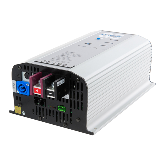
Page 10: Device Layout
3.0 Device layout G3 COMBI Layout Pos. Description ON/OFF Power Switch Potentiometer – Charging current adjustment Charger LED – Green Inverter LED – Blue Battery LED – Red AC charger input connector, type NEUTRIK ( Blue ) Positive voltage DC input terminal Negative voltage DC input terminal External DATA connector RJ12 type ( 6p6 ) External DATA connector RJ12 type ( 6p6 ) -
Page 11: External Connections
3.1 External connections Pin 1 Phoenix Combicon Pin 1 RJ12 type 6p6 connector: Pin# Signal Description - TEMPX1 Reserved for future use User GND ( Fused ) + TEMPX1 Reserved for future use SYNC_IN/OUT Used in option SYNC only DATA Single Wire Clayton Communication Connected to plus pole of the battery switches on the REMOTE... -
Page 12: External Wiring
3.2 External Wiring The two RJ12 6 pole connectors are Limit of the device connected parallel to each other pin to pin. Cable length maximum 3m! -TEMPX1 External NTC User GND Vishay 2381 640 63102 +TEMPX1 1K NTC ... -
Page 13: Neutrik Connectors Assembly
3.3 Neutrik connectors assembly Cable Preparation Wiring Assembling Housing Insert Chuck Bushing BLUE GREY Combination for AC Power IN (only combi models) Combination for AC Power OUT Separation Engagement... -
Page 14: Accessories
4.0 Accessories COMBI Accessories List Description AC output connector, type Neutrik NAC3FCB ( Grey ) Phoenix DATA connector: MSTB 2.5 / 3-ST-5.08 - Green AC input connector , type Neutrik NAC3FCA ( Blue ) 5.0 Operating the device •The aim of this section is to give a brief overview necessary to operate the device and give some proposal how to solve most normal problems occurring during operation of the device. -
Page 15: Charger Section
Charger section: Charge current adjust • The charge current can be adjusted by the potentiometer on the front panel top from 0A up to maximum rated charge current. • See recommended charge current table in section 5.2 Charge Current Setting for correct adjustment. Charge characteristic setup •... -
Page 16: Errors Charger
Errors charger: AC input voltage to low <185VAC (with inverter switched ON) • 1 flash by green LED Note: If the inverter is switched OFF, the charger will operate at even lower voltage than 185VAC, down to 110VAC is in this mode is accepted But with reduced charge current! AC input voltage to high >265VAC •... -
Page 17: Load Search Mode
5.1 Load search mode • In cases where it is preferable to leave the combi switched on, and the load is periodically inactive (switched OFF) the load search mode can be activated. In this mode the combi is partly active and generate a short pulse every 2 second, if a load (>10W resistive) is detected the device switch ON automatically. -
Page 18: Charge Current Setting
5.2 Charge Current Setting • Recommended battery capacity versus charging currents (at 20°C battery temperature) Charge Recommended Battery Current Capacity Range 15 A 75 – 150 Ah 20 A 100 – 200 Ah 25 A 100 – 250 Ah 30 A 150 –... -
Page 19: Charging Stages
5.3 Charging Stages • The charger is a fully automatic 3-stage charger with IUoUo characteristic. Boost charge - Fast flashing green LED • The charger will start in boost charge mode with max pre-set voltage and max charging current. Top charging - Slow flashing green LED •... -
Page 20: Led Code Description
6.0 LED codes description • The Blue LED is for the Inverter section. • Green LED is for the charger section. • Red LED indicating the status of the battery. • Two or all LED can also flash together; see description of the error / status! Blue LED Description. -
Page 21: Batteries
7.0 Batteries WARNING! Working w ith b atteries i s d angerous! Batteries g enerate e xplosive g asses! • T herefore i t i s o f o ut m ost i mportance t hat e ach t ime y ou s erve e quipment i n t he v icinity o f t he b attery, t o follow the battery instructions very accurate. Never smoke or allow a spark or a flame in the vicinity of a ... -
Page 22: Maintenance Batteries
7.1 Maintenance batteries • Performing preventive maintenance on batteries is easy and should occur at least once a month during hot weather and every three months in cold weather. In the case of lead acid batteries the maintenance should include check the electrolyte level for non-sealed wet batteries and the State of Charge (SOC) with hydroscope measurement of specific gravity of the electrolyte and recharging the battery if necessary. -
Page 23: Warranty
• Clayton Power warrants, to the original purchaser only, for a period of 24 months from the date of purchase, that the Clayton Power device will be in good working order when properly installed and operated as described in this manual.
Need help?
Do you have a question about the 1012-50 and is the answer not in the manual?
Questions and answers