
Related Manuals for Clayton Power G3 COMBI


Summary of Contents for Clayton Power G3 COMBI
-
Page 1: User Manual
G3 COMBI Sine Wave Inverter + Battery Charger Type 1012- 50 1024- 30 1312- 80 1512- 80 1524- 40 2012-100 2324- 50 Version 2.0 User Manual Clayton Power GmbH www.claytonpower.com... - Page 2 G3-Combi Page - 2 Clayton Power GmbH...
-
Page 3: Important Basic-Information
The information may contain errors or inaccuracies and represents no commitment whatsoever. Exclusion of liability Clayton Power shall in no event be liable for loss, damages or costs arising from use of this Clayton Power product, or in any way connected with faulty installation, improper operation or incorrect utilization and maintenance. -
Page 4: Table Of Contents
3.5.1 Assembling of Neutrik-plugs....................19 Annex A Information about acid-batteries ...................20 Choosing the best battery ......................20 Battery sizing ........................20 Battery-installation ........................21 Battery maintenance........................21 Check of electrolyte.......................22 Sealed batteries ........................22 Battery storage........................22 Annex B Warranty .........................23 Page - 4 Clayton Power GmbH... -
Page 5: Features And Operation-Functions
230 VAC. This function is particularly well-suited for emergency power (UPS). The obvious advantage is of course that it is always possible to charge and use batteries with one and same unit. Clayton Power Combi, well-suited for emergency power (UPS) True Sine wave Inverter section ... -
Page 6: Inverter Mode
Note: The load search function will remain active if the device is switched ON/OFF by remote. Note: Load search mode will also be deactivated, if battery is disconnected longer than 15 minutes. Page - 6 Clayton Power GmbH... -
Page 7: Charger Mode
Important: The device has a build in fuse – see FUSING section -, do not exceed this limit! Deactivation of charger Disconnecting from AC Grid will stop charging. Note: If the inverter was activated (ON) there will be 230VAC at the grey output connector (discharging) Clayton Power GmbH Page - 7 -... -
Page 8: Charge Current Adjust
AC-supply. Important: for backup-mode, the inverter section always must be switched on! Note: If inverter is switched to OFF, there only will be AC-voltage on AC-Output, when AC- voltage exists at AC-Input of inverter. Page - 8 Clayton Power GmbH... -
Page 9: Led-Indications For Operation And Failfunctions
The battery can explode! Never discharge a battery completely; it will cause permanent damage of the battery! Note: batteries must be able to deliver min. 12W and min. 10,3V before charging can start! Clayton Power GmbH Page - 9 -... -
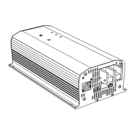
Page 10: Device Layout & Status Indicators
G3-Combi Device layout & status indicators Layout-description G3 COMBI Layout Description Pos. ON/OFF Power Switch Potentiometer – Charging current adjustment Charger LED – Green Inverter LED – Blue Battery LED – Red AC charger input connector, type NEUTRIK Blue Positive voltage DC input terminal... -
Page 11: Specifications
(Slow reaction 3 Sec.) Low battery voltage cut-off 9 VDC 18 VDC 23 VDC (Fast reaction <10mS) Voltage before inverter can 12,75 VDC 25,5 VDC 38,25 VDC switch ON again (after a low battery cut-off) Clayton Power GmbH Page - 11 -... -
Page 12: Batterycharger Specification
(L x W x H) mm Dimension incl. terminals 334 x 198,2 x 116 412 x 198,2 x 116 334 x 198,2 x 116 412 x 198,2 x 116 (L x W x H) mm Weight (kg) Page - 12 Clayton Power GmbH... -
Page 13: Installation
When starting up heavy load with high inrush current (compressors, motors, etc) it is recommended to use cables with a even higher intersection (or shorter length) to prevent under- voltage shut-down of the device Clayton Power GmbH Page - 13 -... -
Page 14: Ac Cables
The table below gives the minimum recommended wire sizes of the mains cable! Device 1012-50 1024-30 1312-80 1512-80 1524-40 2012-100 2324-50 type AC cable 17 AWG 17 AWG 15 AWG 15 AWG 15 AWG 15 AWG AWG 15 = 1.5mm AWG 17 = 1.0mm Page - 14 Clayton Power GmbH... -
Page 15: Fusing
175A slow-blow 1524-40 100A slow-blow Note: The battery fuse does NOT prevent damage in 2012-100 250A slow-blow case of reversed battery polarity; such damage is 2324-50 150A slow-blow not covered by the guarantee! Clayton Power GmbH Page - 15 -... -
Page 16: Mechanical Drawings & Layout Description
G3-Combi Mechanical drawings & layout description 3.3.1 Dimensions MODEL 1512-80 2012-100 2324-50 Page - 16 Clayton Power GmbH... - Page 17 The signal wires of the two connectors are connected parallel, so the pin out and the signals on the correspondending pins are identical Will be introduced and defined in future, only in the case of Combi devices Clayton Power GmbH Page - 17 -...
-
Page 18: Externel Wiring
G3-Combi Externel wiring Page - 18 Clayton Power GmbH... -
Page 19: Device Connection-Plugs
Phoenix data-plug, MSTB 2.5 / 3-ST-5.08 – green AC-Input plug, type Neutrik NAC3FCA – blue 3.5.1 Assembling of Neutrik-plugs Wire preparation Wire connections Housing Insert Chuck Bushing A-Type Plug in (blue) B-type plug-in (grey) Separate Engage Clayton Power GmbH Page - 19 -... -
Page 20: Annex Ainformation About Acid-Batteries
Needed battery capacity (Ah) = Battery voltage (V) x 0,9 (Eff.) Multiply the Ah with 2 to reach the recommended battery Ah size. This will also allow the battery to be cycled only 50% on a regular basis. Page - 20 Clayton Power GmbH... -
Page 21: Battery-Installation
Battery maintenance Performing preventive maintenance on batteries is easy and should occur at least once a month during hot weather and every three months in cold weather. A clean well kept battery will extend Clayton Power GmbH Page - 21 -... -
Page 22: Check Of Electrolyte
Continuous float charging or periodic recharging will prevent batteries from freezing. Do not store the lead acid batteries in discharged state Batteries should be kept at least 3/4 charged, especially during winter weather. Page - 22 Clayton Power GmbH... -
Page 23: Annex Bwarranty
DEVICE MAY BE HAZARDOUS AND MAY CAUSE DAMAGE TO OTHER ELECTRICAL EQUIPMENT AND WILL VOID WARRANTY. Clayton Power warrants, to the original purchaser only, for a period of 24 months from the date of purchase, that the Clayton Power device will be in good working order when properly installed and operated as described in this manual.
Need help?
Do you have a question about the G3 COMBI and is the answer not in the manual?
Questions and answers