
Related Manuals for Marus TL 500

Summary of Contents for Marus TL 500
- Page 1 TL 500 Track Light Owner’s Manual Marus 11727 Fruehauf Drive Charlotte, NC 28273 USA Technical Support: 800-304-5332 FAX: 888-861-9366...
- Page 2 Warranty All of our products sold to and installed by dealers are guaranteed to be free from defects in workmanship and materials for five years from date of purchase. Upholstery is warranted for a period of one year from the date of purchase. During that period, we will replace any defective part at no charge. We WILL NOT be responsible for dealer or service company labor charges or shipping charges to the factory.
-
Page 3: Table Of Contents
Unacceptable Disinfectants ......................17 Conditionally Acceptable Disinfectants* ..................17 Cleaning Reflector and Cover .....................18 Dimensions and Range of Motion - TL 500 Track Light..............19 Dimensions and Range of Motion - Light Head .................21 Service Location - Track Light Power Supply ..................21 Service Location - Light Head ......................22 Electrical Schematics ........................23... -
Page 4: General Information And Warnings
This label states the light model and serial number, electrical specifications, manufacture date and safety Type B Equipment classification. Note the SAMPLE labels shown below. (Protected against electrical shock) Dangerous Voltage Marus Marus 11727 Fruehauf Drive 11727 Fruehauf Drive Charlotte, NC 28273 USA Charlotte, NC 28273 USA... -
Page 5: Safety Notes
SAFETY NOTES The pre-installation must be performed according to the requirements in our ‘Pre-installation Instructions’. As manufacturers of electro-medical products we can assume responsibility for safety-related performance of the equipment only if maintenance, repair and modifications are carried out only by us or agencies we have authorized for this purpose, and if components affecting safe operation of the unit that may be needed are replaced with original parts. -
Page 6: Technical Specifications For The Dental Light
Technical Specifications for the Dental Light Technical Description — Light Replacement Parts for Dental Lights The dental light is used for illuminating the oral The following represents a condensed list of cavity during the performance of dental procedures. replacement parts that may be consumed during The position and direction of the light can be adjusted normal use. -
Page 7: Overview / Replacement Parts
22186 30441 Congratulations on your purchase of the MARUS Track Light! You have chosen a product that will provide years of reliable, trouble-free service. This manual contains instructions for installing, maintaining, and operating the TL 500 model Track light. Fol- lowing these instructions will ensure smooth operation and a long life for your equipment. -
Page 8: Suggested Mounting Methods
Suggested Mounting Methods Stub out wiring at 64” this point (1-1/4”) access hole in 35-1/2” Chair mounting pallet Centerline Ceiling 33-5/8” joists 42” min. Recommended 8‘-0” min. 12’-0” max. 6‘-3” +/-3”... -
Page 9: Suggestions For Suspended Ceiling
Suggestions for Suspended Ceiling CEILING JOISTS 16” ON CENTER MINIMUM SIZE 3/4” PLYWOOD PANEL 77-5/8” x 10” WIDE BE SURE TO BRACE STRUCTURE IN BOTH DIRECTIONS PRE-ASSEMBLED FROM FACTORY LAG BOLTS (NOT INCLUDED) LONG ENOUGH TO GO AT LEAST 3/4” INTO PLYWOOD PANEL... - Page 10 Suggestions for Suspended Ceiling - continued... PREFORMED BRACKETS SUSPENDED PALLET CEILING TRACK 1-1/2” DIA. HOLE 1-1/2” x 3/4” x 1/8” CHANNELS PREFORMED AND BOLTED TO PLYWOOD PALLET PLYWOOD PALLET 77-5/8” 10”...
-
Page 11: Mounting Parallel And Perpendicular
Mounting Parallel and Perpendicular Mounting perpendicular to ceiling joist LAG SCREWS 3/4” PLYWOOD PALLET TO BRIDGE CEILING JOIST Mounting parallel to ceiling joist ALIGN 1-1/2” DIA. on existing construction HOLE WITH HOLE LOCATED IN TRACK 16” 16” 16” 16” BRIDGE BETWEEN CEILING JOIST AT INTERVALS TO ACCEPT MOUNTING SCREWS... -
Page 12: Electrical Requirements
Electrical Requirements The 115VAC/230VAC service line for the track light should be evaluated and installed by a licensed electri- cian in accordance with local electri- cal codes. We recommend that a wall switch be installed in the power supply to fa- cilitate servicing and protect the light transformer in the event of power surges while the light is not in use... - Page 13 Installation Instructions - continued... 3. Be sure that the power to the track light circuit is off and make the necessary electrical connections. We recommend that a licensed electrician make the Set Screw required power connections. Set Screw 4. Assemble the post to the trolley. To do so, remove the electrical bracket and insert the post into the trolley, slide the coiled power cable into the post and insert the cross pin.
- Page 14 (See figure above). 16. This completes the installation of the TL 500 Track Light Assembly. Turn on the light and check for proper operation and balance. The light head is fully assembled and functionally tested prior to leaving the fac-...
-
Page 15: Adjusting The Light-Head's Horizontal Rotation
Adjusting the Light-head’s Horizontal Rotation 1. Remove the plug located at the rear of the pivot housing. Plug 2. Insert a 3/32” hex wrench into the tension screw. Tighten or loosen the tension screw in small increments, test- ing the movement as you go, until the desired tension is achieved. -
Page 16: Adjusting The Light-Head's Third Axis Rotation
Adjusting the Light-head’s Third Axis Rotation 1. Using a 5/64” hex wrench, remove the Back cover back cover of the pivot housing. 2. Using the special tool provided, tighten or loosen the pivot nut in small incre- ments until the desired level is set. 3. -
Page 17: Replacing The Bulb
Replacing the Bulb Bulb For maximum reliability and optimum performance, use replacement bulb no. 70-30441. Shield Warning! Do not attempt to remove a bulb until it has been allowed to cool for at least two minutes. The bulb is a two-prong push-in type. To replace a bulb: 1. -
Page 18: Adjusting The Auto-Switch(Optional)
Adjusting the Auto-Switch(Optional) Contact turns light off Range of adjustment The Switch assembly is clipped onto the light arm tension rod. To change the position at which the light Tension rod activates: Auto switch 1. To adjust the position at which the auto switch activates, simply slide the switch bracket towards or away from the switch bracket until the desired Slide actuator bracket... -
Page 19: Cleaning The Light
Cleaning the Light The equipment can be cleaned with a solution of mild detergent and warm water. A variety of surface disinfectants are available for use in dental treatment rooms. Some of these can cause discoloration of painted, plated or anodized surfaces with repeated use. -
Page 20: Cleaning Reflector And Cover
Cleaning the Light, Continued Cleaning Reflector and Cover NOTE: Use only denatured alcohol to clean the glass reflector. Use only mild soap and water to clean the plastic reflector cover. Do not use any solvents, abrasives, abrasive cloths or cleaners, as they may damage the coated surface of the reflector. -
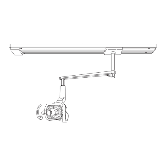
Page 21: Dimensions And Range Of Motion - Tl 500 Track Light
Dimensions and Range of Motion - TL 500 Track Light 79” 14.75” 58.25” 10.5” 28.75” 54° 288°... - Page 22 Dimensions and Range of Motion -TL 500 Track Light 270° 12” - 39”* 15° 16.5” 42° *DIMENSION VARIES DEPENDING UPON CEILING HEIGHT. SEE DCI EQUIPMENT CATALOG FOR CHART REGARDING TRACK LIGHT SUSPENSION TUBE LENGTHS.
-
Page 23: Dimensions And Range Of Motion - Light Head
Dimensions and Range of Motion - Light Head 120° 120° 40° 140° Service Location - Track Light Power Supply 6-32 Phillips Head Screw Transformer Cover Transformer Insulator Fuses Transformer Ground Power Location Switch... -
Page 24: Service Location - Light Head
Service Location - Light Head ON/OFF Toggle Switch Bulb Replacement... -
Page 25: Electrical Schematics
DENT AL LIGHT BLA CK WHITE GREEN CONNECT OR 4 AMP FUSE W/HOLDER PIN LOCA TION TRANSFORMER 230V 115V BLA CK WHITE YELLO W 1 15V POWER SUPPL Y CONNECT OR PIN LOCA TION TL 500 Track Light Electrical Schematic - 115V... - Page 26 PIN LOCATION LAMP ARM SWITCH DENTAL LIGHT BLACK WHITE GREEN 2 AMP FUSE W/HOLDER (2 PLACES) CONNECTOR PIN LOCATION TRANSFORMER 230V YEL/GRN 115V BLACK WHITE GREEN 230V POWER SUPPLY CONNECTOR PIN LOCATION TL 500 Track Light Electrical Schematic - 230V...
-
Page 27: Electromagnetic Compatibility
ELECTROMAGNETIC COMPATIBILITY MEDICAL ELECTRICAL EQUIPMENT ELECTROMAGNETIC COMPATIBILITY (Instructions for use) ELECTROMAGNETIC COMPATIBILITY Electrical medical devices are subject to special EMC safety measurements and as a result the equipment must be installed according to the installation instruction manual. PORTABLE ELECTRONIC DEVICES Portable and mobile high frequency electronic communications equipment may interfere with electronic medical devices. - Page 28 ELECTROMAGNETIC COMPATIBILITY Guidance and manufacturer‘s declaration-electromagnetic immunity This product is intended for use in the electromagnetic environment specified below. The customer or the user of this product should ensure that it is used in such an environment. COMPLIANCE LEVEL ELECTROMAGNETIC IMMUNITY TEST IEC60601 TEST LEVEL ENVIRONMENT GUIDANCE...
- Page 29 ELECTROMAGNETIC COMPATIBILITY Guidance and manufacturer's declaration-electromagnetic immunity This product is intended for use in the electromagnetic environment specified below. The customer or the user of this product should assure that it is used in such an environment. Immunity Test IEC60601 Test Level Compliance Level ELECTROMAGNETIC ENVIRONMENT GUIDANCE...
- Page 30 ELECTROMAGNETIC COMPATIBILITY Guidance and manufacturer‘s declaration-electromagnetic emissions This product is intended for use in the electromagnetic environment specified below. The customer or the user should assure that it is used in such an environment. Emissions Test Compliance Electromagnetic Environment guidance RF emissions Group 1 This product uses RF energy only for its internal...
-
Page 31: Checklist
CHECKLIST Verify the following after installation or servicing of the light: All manuals are present. All labels are present and legible. No mechanical damage on new installations. The arm is balanced and the friction adjustment is adjusted so that the light has no noticeable drift in the upper and lower positions. - Page 35 Purchase Information Write in the model and serial numbers below for all applicable equipment such as the chair, unit light and unit control head. MODEL: ____________________________ DATE PURCHASED: __________________ SERIAL NUMBER: ___________________ DATE INSTALLED: ___________________ DEALER NAME AND ADDRESS: MODEL: ____________________________ _____________________________ SERIAL NUMBER: ___________________ _____________________________...
- Page 36 11727 Fruehauf Drive Charlotte, NC 28273 USA Technical Support: 800-304-5332 FAX: 888-861-9366 92353 Rev. 5 • 02/12 •...
Need help?
Do you have a question about the TL 500 and is the answer not in the manual?
Questions and answers