
Related Manuals for Marus CL1000

Summary of Contents for Marus CL1000
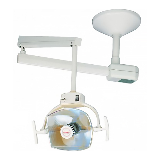
- Page 1 CL1000 Ceiling Light OWNER’S MANUAL Marus 11727 Fruehauf Drive Charlotte, NC 28273 USA...
-
Page 2: Technical Support
Warranty The Marus Light was thoroughly inspected and tested in accordance with rigid specifications and standards of Marus quality. All of our products sold to and installed by dealers are guaranteed to be free from defects in workmanship and materials for five years from date of purchase - providing all installation and service is done in accordance with procedures as outlined in our instructions. -
Page 3: Table Of Contents
Table of Contents General Information ..........................2 Definition of Symbols ........................2 Product Disposal ..........................2 Interference with Electromedical Devices ..................2 Incompatible Devices and/or Accessories ..................2 Obtaining Technical Literature ......................2 Product Identification ........................2 Safety Notes ............................3 Storage Conditions.......................... -
Page 4: General Information
Note the SAMPLE labels Electrical Testing Lab shown below. Identification mark that indicates the product Marus Marus complies with the health & safety requirements 11727 Fruehauf Drive 11727 Fruehauf Drive Charlotte, NC 28273 USA Charlotte, NC 28273 USA as published by European Directives. -
Page 5: Safety Notes
Safety Notes The pre-installation must be performed according to the requirements in our ‘Pre-installation Instructions’. As manufacturers of electro-medical products we can assume responsibility for safety-related performance of the equipment only if maintenance, repair and modifications are carried out only by us or agencies we have authorized for this purpose, and if components affecting safe operation of the unit that may be needed are replaced with original parts. -
Page 6: Technical Specifications For The Dental Light
Technical Specifications for the Dental Light Technical Description — Light Replacement Parts for Dental Lights The dental light is used for illuminating the oral cav- The following represents a condensed list of ity during the performance of dental procedures. The replacement parts that may be consumed during position and direction of the light can be adjusted as normal use. -
Page 7: Cleaning The Light
Cleaning the Light The equipment can be cleaned with a solution of mild detergent and warm water. A variety of surface disinfectants are available for use in dental treatment rooms. Some of these can cause discoloration of painted, plated or anodized surfaces with repeated use. This can be minimized by careful adherence to the disinfectant manufacturer’s instructions and by frequent washing with soap and water. -
Page 8: Cleaning Reflector And Cover
CLEANING YOUR LIGHT Cleaning Reflector and Cover NOTE: Use only denatured alcohol to clean the glass reflector. Use only mild soap and water to clean the plastic reflector cover. Do not use any solvents, abrasives, abrasive cloths or cleaners, as they may damage the coated surface of the reflector. Be sure the electrical supply is turned off and the light is cool before attempting any cleaning or polishing. -
Page 9: Dimensions
Dimensions 12” 21-1/2” - 26” 23 1/2” 28” TRAVEL Figure 1 Location A typical location for mounting the ceiling mount light is relation to the dental chair for a right-handed operator is shown in Figure 2. Mounting for a left-handed operator would be mounted on the opposite side of the chair. This mounting location can be altered to suit the individual’s preference or the building construction. -
Page 10: Suggested Mounting Methods
Suggested Mounting Methods TYPICAL POSITION OF CEILING MOUNT IN RELATION TO DENTAL CHAIR MOUNTING LOCATION 12” FOR RIGHT-HANDED OPERATOR 18” 18” MOUNTING LOCATION 12” FOR LEFT-HANDED OPERATOR Figure 2... -
Page 11: Suggested Installation On Wood Framed Ceiling
Suggested Installation on Wood Framed Ceiling CEILING JOISTS 16” O.C. POWER SUPPLY 1 INCH CONDUIT MOUNTING PLATE w/ COLLAR FINISHED CEILING MATERIAL POWER CONDUIT COMES THROUGH HOLE 2-1/2” OFFSET FROM CENTER. NEW CONSTRUCTION Figure 3 CEILING JOISTS 16” O.C. 1 INCH (6) 1/4”... -
Page 12: Wood Structure For Suspended Ceiling
Suggested Installation on Suspended Ceiling SUGGESTED INSTALLATION ON SUSPENDED CEILING SUGGESTED INSTALLATION ON SUSPENDED CEILING FIXED CEILING FIXED CEILING CEILING JOIST MOUNTING PLATE w/ COLLAR & POST CEILING JOIST MOUNTING PLATE w/ COLLAR & POST SUSPENDED CEILING COVER SUSPENDED CEILING COVER MOUNTING PLATE w/ COLLAR &... -
Page 13: Metal Structure For Suspended Ceiling
Metal Structure for Suspended Ceiling USE METAL MASONRY ANCHOR WHEN REQUIRED 3/8” BOLTS FINISHED CEILING SUSPENDED CEILING LEVELING PLATE 1-1/2” x 3/4” x 1/8” CHANNELS WELDED TO PLATE STEEL PLATE 1/8” THICK COVER (6) 3/8” BOLTS EACH BOLT MUST SUPPORT AT LEAST 75 LBS. -
Page 14: Ceiling Light Installation Instructions
Ceiling Light Installation Instructions 1. Refer to figure #2 for proper location of the ceiling light in relation to the dental chair. Although traditional methods dictate mounting the light to the left side of the chair for a right-handed operator and vice-versa for left-handed, careful consideration should be given to mounting location, especially to prevent interference with x-ray units. - Page 15 11. Check the light for freedom of movement and for any drift when positioned. Recheck the post and make any necessary leveling adjustments. Raise the ceiling plate cover to the top of the pole and tighten the set screw of the cover stop collar to hold the cover in place. 12.
- Page 16 Power Supply Ceiling Mounting Access Hole Plate Junction Box Safety Bolt Post Socket Suspension Tube or Ground Ceiling Post Terminal (Refer to chart on Pg. 4) Stop Collar Ceiling Plate Cover Coiled Cord Figure 9 Locking Tab Retaining Collar Set Screw Suspension Tube or Ceiling Post (Refer to chart on Pg.
-
Page 17: Overview / Replacement Parts
Spare Bulb The Marus light is equipped with a spare bulb in the rear of the light head. If the bulb should happen to fail, replace it with the spare bulb provided. See Bulb Replacement section, page 16. -
Page 18: Bulb Removal And Replacement
Adjustments Bulb Removal and Replacement Note: For maximum reliability and optimum operation, always use Marus replacement bulb #014R207. WARNING! Do not attempt to remove the bulb for 2 minutes after the light has been turned off or until the bulb has cooled. -
Page 19: Light Focus Adjustments
Light Focus Adjustments Note: Focus adjustment should be checked each time a new bulb is installed. 1. Place a white paper or cardboard sheet in front of the light* 27 inches from the foremost surface of the bulb shield (or turn the light toward wall at the same distance). 2. - Page 20 Yoke Pivot Friction Adjustment Horizontal Note: If the light head pivots too freely horizontally, an adjustment can be made as follows: 1. Remove the four screws located at the rear of the light head using a 7/64 hex head wrench. Remove the rear cover (see figure 14).
-
Page 21: Flex Arm Adjustment
Flex Arm Adjustment Vertical 1. Remove the two flex arm cover screws using a flat head screwdriver. (See figure 15). 2. Remove the flex arm cover. 3. Using a 1/2” wrench or socket, adjust the tension bolt until the desired tension is set. Turn clockwise for more tension, counter-clockwise for less tension. -
Page 22: Electromagnetic Compatibility
ELECTROMAGNETIC COMPATIBILITY MEDICAL ELECTRICAL EQUIPMENT ELECTROMAGNETIC COMPATIBILITY (Instructions for use) ELECTROMAGNETIC COMPATIBILITY Electrical medical devices are subject to special EMC safety measurements and as a result the equipment must be installed according to the installation instruction manual. PORTABLE ELECTRONIC DEVICES Portable and mobile high frequency electronic communications equipment may interfere with electronic medical devices. - Page 23 ELECTROMAGNETIC COMPATIBILITY Guidance and manufacturer‘s declaration-electromagnetic immunity This product is intended for use in the electromagnetic environment specified below. The customer or the user of this product should ensure that it is used in such an environment. COMPLIANCE LEVEL ELECTROMAGNETIC IMMUNITY TEST IEC60601 TEST LEVEL ENVIRONMENT GUIDANCE...
- Page 24 ELECTROMAGNETIC COMPATIBILITY Guidance and manufacturer's declaration-electromagnetic immunity This product is intended for use in the electromagnetic environment specified below. The customer or the user of this product should assure that it is used in such an environment. Immunity Test IEC60601 Test Level Compliance Level ELECTROMAGNETIC ENVIRONMENT GUIDANCE...
- Page 25 ELECTROMAGNETIC COMPATIBILITY Guidance and manufacturer‘s declaration-electromagnetic emissions This product is intended for use in the electromagnetic environment specified below. The customer or the user should assure that it is used in such an environment. Emissions Test Compliance Electromagnetic Environment guidance RF emissions Group 1 This product uses RF energy only for its internal...
-
Page 26: Electrical Schematics
Electrical Schematics 230V CL1000 Ceiling Light - 115V... - Page 27 Electrical Schematics 230V 115V CL1000 Ceiling Light- 230V...
-
Page 28: Checklist
CHECKLIST Verify the following after installation or servicing of the light: All manuals are present. All labels are present and legible. No mechanical damage on new installations. The arm is balanced and the friction adjustment is adjusted so that the light has no noticeable drift in the upper and lower positions. - Page 31 Purchase Information Write in the model and serial numbers below for all applicable equipment such as the chair, unit light and unit control head. MODEL: ____________________________ DATE PURCHASED: __________________ SERIAL NUMBER: ___________________ DATE INSTALLED: ___________________ DEALER NAME AND ADDRESS: MODEL: ____________________________ _____________________________ SERIAL NUMBER: ___________________ _____________________________...
- Page 32 Marus 11727 Fruehauf Drive Charlotte, NC 28273 USA Technical support: 800-304-5332 Web Site: www.marus.com 70-050R228 Rev. 11 •02/12...
Need help?
Do you have a question about the CL1000 and is the answer not in the manual?
Questions and answers