Table of Contents
Advertisement
Quick Links
I
NDIRECT
A Spanish language version of these instructions is available by contacting
the manufacturer listed on the rating plate.
La version espanola de estas instruccions se puede obtener al escribirle a
la fábrica cuyo nombre aparece in la placa de especificaciones.
INSTALLATION/OPERATING MANUAL
WITH PARTS LISTING AND TROUBLESHOOTING GUIDE
For your family's comfort, safety, and convenience, we
recommend this water heater be installed and serviced by a
plumbing professional.
-
FIRED
WATER HEATER
To avoid damage or injury, there
must be no materials stored
against the indirect water heater
and proper care shall be taken to
avoid unnecessary contact
(especially by children) with the
indirect water heater.
Do not store or use
gasoline or other
flammable liquids in
the vicinity of this
water heater or any
other appliance.
238-43480-00E REV 01/08 Doc. 11045
WARNING
Advertisement
Table of Contents

Related Manuals for Laars INDIRECT-FIRED


Summary of Contents for Laars INDIRECT-FIRED
- Page 1 NDIRECT FIRED WATER HEATER A Spanish language version of these instructions is available by contacting the manufacturer listed on the rating plate. La version espanola de estas instruccions se puede obtener al escribirle a la fábrica cuyo nombre aparece in la placa de especificaciones. WARNING To avoid damage or injury, there must be no materials stored...
- Page 2 CONGRATULATIONS! You have just purchased one of the finest water heaters on the market today! This installation, operation, and instruction manual will explain in detail the installation and maintenance of your new Indirect water heater. We strongly recommend that you contact a plumbing professional for the installation of this water heater.
-
Page 3: Table Of Contents
CAUTION The maximum boiler water supply temperature to the indirect heat exchanger must not exceed 240°F (115°C). NOTICE Insulation blankets are not required for this water heater. This water heater meets or exceeds the ASHRAE/IES 90.1b standards with respect to insulation and standby loss requirements. TABLE OF CONTENTS IMPORTANT INFORMATION…………….….. -
Page 4: Important Information
SECTION I IMPORTANT INFORMATION -READ CAREFULLY- The equipment must be installed in accordance with those installation regulations required in the area where the installation is to be made. These regulations must be carefully followed in all cases. Authorities having jurisdiction shall be consulted before installations are made. - Page 5 Important Information continued- DANGER DO NOT store or use gasoline or other flammable, combustible, or corrosive vapors and/or liquids in the vicinity of this or any other appliance. IF YOU SMELL GAS: DO NOT try to light any appliance. DO NOT touch any electric switch; do not use any telephone in your building.
- Page 6 Important Information continued- WARNING Installation is not complete unless a pressure and temperature relief valve is installed into the side of the water heater. See the Water Connections section of this manual for details. This water heater contains very hot water under high pressure. Do not unscrew any pipe fittings or attempt to disconnect any components of this water heater without positively assuring the water is cool and has no pressure.
- Page 7 Important Information continued- WARNING It is the responsibility of the installing contractor to see that all controls are correctly installed and are operating properly when the installation is complete. DO NOT operate the water heater with jumpered or absent controls or safety devices. DO NOT tamper with or alter the water heater and/or controls.
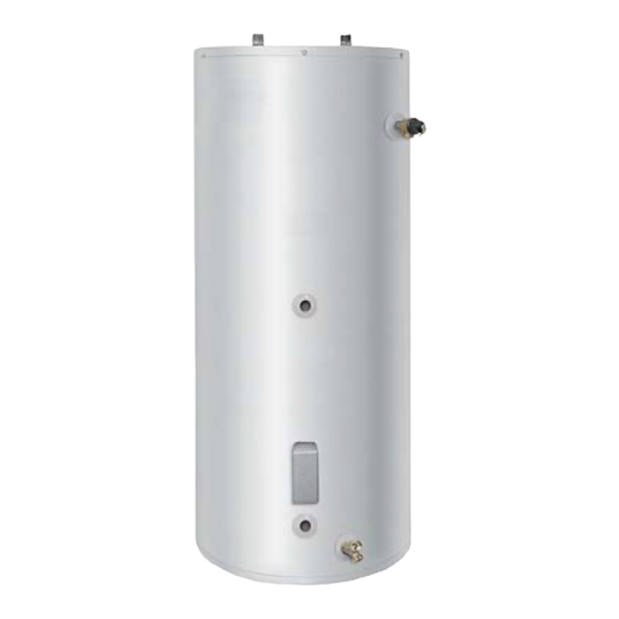
- Page 8 SECTION II SPECIFICATIONS Figure 1 – Tank Layout Table 1: Water Heater Dimension (Inches) MODEL 30-Gal. / Res. 33-5/8 28-1/4 34-3/8 5-3/8 27-1/2 40-Gal. / Res. 29-3/4 36-3/4 5-3/8 27-1/2 40-Gal. “R” / Res. 41-1/8 34-3/8 41-7/8 5-3/8 27-1/2 50-Gal. / Res. 29-3/4 36-3/4 5-3/8...
- Page 9 Specifications continued- Table 2: Water Heater Capacities Tank Coil Dry Weight Wet Weight Capacity Volume (Lbs) (Lbs) MODEL (Gal) (Gal) 30-Gal. / Res. 40-Gal. / Res. 40-Gal. “R” / Res. 50-Gal. / Res. 50-Gal. “R” / Res. 65-Gal. / Res. 65-Gal.
- Page 10 Specifications continued- Table 4: Water Heater Performance Approximate Maximum First Continuous Boiler Output Hour Rating Draw Rating Needed For (Gal/Hr) @ (Gal/Min) @ Ratings 140 °F 115 °F 140 °F 115 °F MODEL (BTU/hr) 30-Gal. / Res. 220,000 40-Gal. / Res. 220,000 40-Gal.
- Page 11 94,100 Btu/hr for residential models and 180,300 Btu/hr for commercial models. Potable water temperature is limited to below 210°F and nominal water- containing capacity is below 120 gallons for all indirect-fired models. Accordingly, per Part HLW-101.2, Section IV of the ASME Boiler and Pressure Vessel Code, all indirect-fired products listed are exempted from compliance with the code.
-
Page 12: Iii- General Information
SECTION III GENERAL INFORMATION FEATURES This water heater contains the following features: HEAT EXCHANGER -- The heat exchanger (coil) has 1” NPT female fittings. These water heaters with single-wall heat exchangers meets the Uniform Plumbing Code for installation in all potable water systems provided that: •... - Page 13 General Information continued- TEMPERATURE AND PRESSURE RELIEF VALVE WARNING Keep clear of the combination temperature and pressure relief valve discharge line outlet. The discharge may be hot enough to cause scald injury. The water is under pressure and may splash. For protection against excessive temperatures and pressure, install temperature and pressure protective equipment required by local codes, but not less than a combination temperature and pressure relief valve certified by a...
- Page 14 General Information continued- WARNING Install a discharge line so that water discharged from the temperature and pressure relief valve will exit within six (6) inches above, or any distance below, the structural floor and cannot contact any live electrical part. The discharge line is to be installed to allow for complete drainage of both the temperature and pressure relief valve and the discharge line.
-
Page 15: Iv- Pre-Installation
IMPORTANT DECISIONS REQUIRED BEFORE INSTALLATION SIZING 1. Boiler DOE Heating Capacity – The indirect-fired water heater will provide the rated performance only if used in conjunction with a heat source with a DOE heating capacity (Boiler Output) at least as much as the minimum noted in Table 3. - Page 16 SYSTEM ZONE CONTROL The indirect-fired water heater must be installed as a zone separate from the space heating system. The domestic hot water zone’s piping and circulator must be sized for a minimum flow rate with all zones in use and a maximum flow rate with only the water heater in use.
- Page 17 Pre-installation continued- DOMESTIC HOT WATER PRIORITY Two options are available, Priority and Non-Priority. 1. Priority – Demand for space heating is interrupted or postponed until the domestic hot water demand is satisfied. This option provides maximum delivery of domestic hot water. Priority is recommended when: a) Boiler net output is 100,000 Btu per hour or less, or b) When boiler output required to satisfy domestic hot water...
-
Page 18: Recommended Service Clearances
Pre-installation continued- Component Location CAUTION This water heater must be located in an area where leakage of the tank, water line connections, or the temperature and pressure relief valve will not result in damage to the area adjacent to the water heater or to lower floors of the structure. -
Page 19: Appliance Location
Pre-installation continued- Appliance Location 1. Boiler Location – Locate the indirect-fired water heater as close to the boiler as practical. 2. Fixture Locations – For fastest delivery of hot water, place the indirect-fired water heater close to points of use. -
Page 20: Water Connections
SECTION V WATER CONNECTIONS WARNING FAILURE TO INSTALL AND MAINTAIN A NEW, LISTED TEMPERATURE AND PRESSURE RELIEF VALVE WILL RELEASE THE MANUFACTURER FROM ANY CLAIM WHICH MIGHT RESULT FROM EXCESSIVE TEMPERATURE AND PRESSURES. Hydrogen gas can be produced in an operating water heater that has not had water drawn from the tank for a long period of time. - Page 21 Water Connections continued- INSTALL TEMPERATURE AND PRESSURE RELIEF VALVE (if not factory installed) WARNING Temperature and pressure relief valve discharge piping must be piped near the floor to eliminate potential of severe burns. Do not pipe in any area where freezing could occur. Do not install any shut-off valves, plugs or caps to the temperature and pressure relief valve or piping.
- Page 22 The use of shut-off valves and unions are recommended for future service convenience. The use of an air separator and vent is recommended to eliminate air in the system. Pipe and fittings between the boiler and indirect-fired water heater must be ¾” diameter or larger. CAUTION Maximum boiler water supply temperature to the indirect heat exchanger must not exceed 240°F (116°C).
- Page 23 The use of an air separator and vent is recommended to eliminate air in the system. Pipe and fittings between the boiler and indirect-fired water heater must be ¾” diameter or larger. Figure 3 - Water Boiler Piping with Circulators...
- Page 24 Water Connections continued- CONNECT STEAM BOILER SUPPLY PIPING Figure 4 represents a typical steam boiler connection diagram. Refer to the boiler installation manual or contact the boiler manufacturer for an appropriate piping diagram. The use of a union, shut-off valves, and a drain valve is recommended for future service convenience.
- Page 25 Electrical power may be from more than one source. Make sure all power is off before attempting any electrical work. This indirect-fired water heater is supplied with an aquastat temperature control. This aquastat must be installed in the aquastat well location of the water heater. Refer to Figure 5. Remove the cover and loosen the clamping screws.
- Page 26 Electrical Connections continued- Figure 5 - Aquastat Control SECTION VII OPERATING INSTRUCTIONS WARNING Water heaters are heat-producing appliances. To avoid damage or injury there must be no materials stored against the water heater, and proper care must be taken to avoid unnecessary contact (especially by children) with the water heater.
- Page 27 Electrical Connections continued- SYSTEM START-UP Follow boiler installation instructions to place boiler in operation. SEQUENCE OF OPERATIONS 1. Aquastat senses stored water temperature drops below desired setting. a. Domestic hot water priority only: Normally closed contacts open to interrupt space heating. 2.
- Page 28 Electrical Connections continued- Table 8 details the approximate relationship of water temperature and time with regard to scald injury and may be used as a guide in determining the safest water temperature for your applications. APPROXIMATE TIME/TEMPERATURE RELATIONSHIPS IN SCALDS 120°F More than 5 minutes 125°F...
- Page 29 Repeat step SECTION VIII MAINTENANCE This indirect-fired water heater is intended to provide a service life of many years. Components that require service, however, may be subject to failure. Failure to use the correct procedures or parts in these circumstances may make the water heater unsafe.
- Page 30 Maintenance continued- CAUTION Before manually operating the valve, make sure that a drain line has been attached to the valve to direct the discharge to an open drain. Failure to take this precaution could mean contact with extremely hot water discharging from the valve during this checking operation.
- Page 31 Maintenance continued- a. Turn the water heater electricity off for the zone containing the indirect-fired heater. Flow water until the discharge is cool or allow enough time for the potable water to cool naturally. Connect a hose to the drain valve. Locate the hose’s discharge in an area where any remaining hot water will not cause any damage or injury.
-
Page 32: Vi- Electrical Connections
SECTION IX TROUBLE SHOOTING GUIDE PROBLEM CAUSE SOLUTION No hot water at Boiler does not Refer to boiler installation faucet. operate. instructions. Check main service switch. Check fused disconnect. Circulator does Check power supply. not operate. Replace as necessary. Improper aquastat Turn tank aquastat to setting or appropriate setting. - Page 33 Trouble Shooting Guide continued- PROBLEM CAUSE SOLUTION Insufficient hot Aquastat setting Adjust aquastat to higher water. too low. setting. See Section VII. Undersized boiler Rewire for priority. with no priority to domestic hot water. Peak use of hot Determine peak usage water is greater and compare to tank than tank storage...
-
Page 34: Parts List
SECTION X PARTS LIST PART NAME & DESCRIPTION 1. Aquastat Control 7. Drain Valve 2. Aquastat Well 8. Jacket Head Pan 3. Anode 9. Hole Closure 4. Diptube 10. Heat Exchanger Escutcheon 5. Outlet Nipple 11. Drain Escutcheon 6. T&P Relief Valve 12. - Page 35 Contact your supplier or plumbing professional for replacement parts or contact the company at the address given on the rating plate of the water heater. Provide the part name, model, and serial numbers of the water heater when ordering parts. READ THE WARRANTY FOR A FULL EXPLANATION OF THE LENGTH OF TIME THAT PARTS AND THE WATER HEATER ARE WARRANTED.
- Page 36 (Customer Service, Service Advisors) 20 Industrial Way, Rochester, NH 03867 • 603.335.6300 • Fax 603.335.3355 (Applications Engineering) 1869 Sismet Road, Mississauga, Ontario, Canada L4W 1W8 • 905.238.0100 • Fax 905.366.0130 www.Laars.com Litho in U.S.A. © Laars Heating Systems 0810 Document 11045...
Need help?
Do you have a question about the INDIRECT-FIRED and is the answer not in the manual?
Questions and answers