Advertisement
Quick Links
Installation and Operation Instructions
FOR YOUR SAFETY: This product must be installed and serviced by a professional service technician,
qualified in hot water heater installation and maintenance. Improper installation and/or operation could
create carbon monoxide gas in flue gases which could cause serious injury, property damage, or death.
Improper installation and/or operation will void the warranty.
If the information in this manual is not followed exactly, a fire or explosion may result
causing property damage, personal injury or loss of life.
Do not store or use gasoline or other flammable vapors and liquids in the vicinity of this or
any other appliance.
• Do not try to light any appliance.
• Do not touch any electrical switch; do not use any phone in your building.
• Immediately call your gas supplier from a nearby phone. Follow the gas supplier's
instructions.
• If you cannot reach your gas supplier, call the fire department.
Installation and service must be performed by a qualified installer, service agency, or gas
supplier.
NOTE: This manual is to be used in conjunction
with Document 1025, Installation and Operation
Instructions for Mini-Therm II JV boilers.
WARNING
WHAT TO DO IF YOU SMELL GAS
and Operation
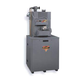
Instructions for
Mini-Combo II
(Models MCT, MCS)
Residential Gas-Fired
Space/Water Heater
Document 8001D
Installation
Advertisement

Related Manuals for Laars Mini-Combo II MCT


Summary of Contents for Laars Mini-Combo II MCT
- Page 1 Installation and Operation Instructions Document 8001D Installation and Operation Instructions for Mini-Combo II (Models MCT, MCS) Residential Gas-Fired Space/Water Heater NOTE: This manual is to be used in conjunction with Document 1025, Installation and Operation Instructions for Mini-Therm II JV boilers. FOR YOUR SAFETY: This product must be installed and serviced by a professional service technician, qualified in hot water heater installation and maintenance.
-
Page 2: Table Of Contents
LAARS HEATING SYSTEMS Page 2 TABLE OF CONTENTS SECTION 1. SECTION 2. General Information Installation Introduction ........... 3 Location ............3 Heater Placement ......... 3 Piping ............5 Wiring ........... 5, 6, 7 Sequence of Operation ........ 9... -
Page 3: General Information
Mini-Combo II Page 3 • Studies have indicated that dangerous bacteria SECTION 1. can form in potable water distribution system if General Information certain minimum water temperatures are not maintained. Contact local health department for more information. WARNING This manual supplies information on the application, installation and operation of the indirect water SECTION 2. - Page 4 LAARS HEATING SYSTEMS Page 4 System Check Valve (Sizes 50 & 25) 25 635 Vent Damper* Check Valve (Size 75 & 100) Mini-Therm Boiler (50-125) FRONT VIEW SIDE VIEW Tank Water Relief Valve Mounted 1372 Tank Pump Outlet Tank Aquastat...
-
Page 5: Piping
Mini-Combo II Page 5 2C. Piping 2D. Wiring • To Prevent damage to the unit, all soldering is to Priority System: Under this wiring the storage be done prior to assembling the cold and hot tank will be supplied before space heating. This will water, and any other connections to the tank. - Page 6 LAARS HEATING SYSTEMS Page 6 OPTIONAL HIGH AQUASTAT VENT DAMPER LIMIT TRANSFORMER RECEPTACLE* 115/60HZ 115V POWER SUPPLY WALL NEUTRAL THERMOSTAT (FIELD SUPPLIED) GROUNDING CONDUCTOR ZONE PUMP RELAY TANK TERMINAL AQUASTAT STRIP JUMPER PUMP (FIELD SUPPLIED) POWER VENTER FAN PROVING SWITCH...
- Page 7 Mini-Combo II Page 7 *Some Canadian units are supplied with vent damper jumper plug. Do not remove jumper unless vent damper is to be installed. Figure 6. MCT Schematic.
- Page 8 LAARS HEATING SYSTEMS Page 8 *Some Canadian units are supplied with vent damper jumper plug. Do not remove jumper unless vent damper is to be installed. Figure 7. MCS Schematic.
-
Page 9: Sequence Of Operation
Mini-Combo II Page 9 2E. Sequence of Operation 115 Volts Supply Transformer Tank Stat (common) Vent Damper Motor Domestic Demand Heating Demand (N.C.) (N.O.) Tank Pump Heating Pump (energized) (energized) High Limit Switch Vent Damper Open Power Vent Fan Switch (optional) Safety Limit Switches Main Gas Valve... - Page 10 LAARS HEATING SYSTEMS Page 10 Figure 9. Parts Identification.
- Page 11 Mini-Combo II Page 11 Part # Description 20085700 Weldment, Panel, Base 20085600 Weldment, Panel, Top 20086300 Weldment, Panel, Door 20086400 Panel, Side, Right 20127900 Weldment, Panel, Side, Left 20085900 Panel, Rear 20086500 Panel, Access 20084000 Bracket, Mounting, Left 20085400 Bracket, Support, Tank P2015400 Tee, Blk, 1¼"...
- Page 12 6000 Condor Drive, Moorpark, CA 93021 • 805.529.2000 • FAX 805.529.5934 20 Industrial Way, Rochester, NH 03867 • 603.335.6300 • FAX 603.335.3355 480 S. Service Road West, Oakville, Ontario, Canada L6K 2H4 • 905.844.8233 • FAX 905.844.2635 www.laars.com Litho in U.S.A. © Laars Heating Systems 0009 Document 8001D...
Need help?
Do you have a question about the Mini-Combo II MCT and is the answer not in the manual?
Questions and answers