
Related Manuals for Lovol Lovol Phaser Series

Summary of Contents for Lovol Lovol Phaser Series
- Page 1 User’s handbook World Power Inherits From leading Technology Lovol Phaser Series, Lovol 1000 Series Part No.: T768050005 Tianjin Lovol Engines Co.,Ltd.
- Page 2 USER’S HANDBOOK Lovol Phaser Series, Lovol 1000 Series 3, 4 and 6 cylinder diesel engines for industrial agricultural and vehicle use Tianjin Lovol Engines Co., Ltd Jinwei Road, Beichen District, Tianjin, China Postcode: 300402...
- Page 3 Lovol Phaser Series Lovol 1000 Series...
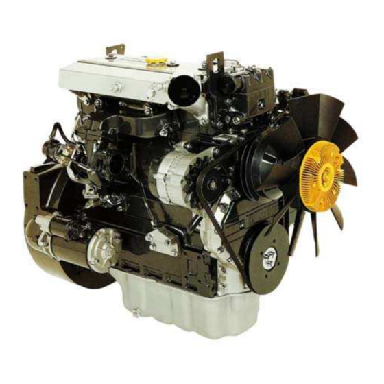
- Page 4 EGR engine of Lovol Phaser Series Engine of Lovol 1000 Series...
-
Page 5: Table Of Contents
Contents: General information…..………………………………………..1 Engine Views……...………………………………………………..2 Instruction for operation.………………………………………….3 Preventive maintenance……………………………………………4 Engine fluids………………………………………………………5 Fault diagnosis…………..………………………………………….6 Engine preservation…………………………………………………7 Parts and service……………………………………………………8 General information…….…………………………………………9 Fuel and injection Pump…………………………………………10 Turbocharger…………………………………………………………11 Hydraulic pump……………………………………………………12 EGR intake system…………………………………………………13... -
Page 6: General Information
General information Introduction..................1.02 How to care for your engine ............1.03 Safety precautions................1.04 Engine identification...............1.05 Lifting device for engine..............1.06 1.01... -
Page 7: Introduction
Introduction Lovol Phaser series and Lovol 1000 Series engines are the latest development from Tianjin Lovol Engines Co., Ltd. They have inherited the nearly 100 year’s engine production experience in European and world leading technology. For the need of global power, they are designed and developed the classical power with European heritage and modern latest technology. -
Page 8: How To Care For Your Engine
How to care for your engine Warning! Read "Safety precautions" remember them. They are given for your protection and must be applied at all times. This handbook is to assist you to maintain and operate your engine correctly. To obtain the best performance and the longest life from your engine, you must ensure that the maintenance operations are done at the intervals indicated in "Preventive maintenance". -
Page 9: Safety Precautions
Safety precautions These safety precautions are important. You must refer also to the local regulations in the country of use. Some items only apply to specific applications. Only use these engines in the type of application for which they have been designed. Do not change the specification of the engine. -
Page 10: Engine Identification
TA------Turbocharged air-intercooled engine Engine identification Engines used for generator sets have a similar system of model identification, for example: 1003TG、1004TG、1006TAG Phaser series for vehicle use consists of a range of 1003------3 cylinder engine both four and six cylinder engines. Each type of 1004------4 cylinder engine cylinder will have four basic engine types, naturally 1006-------6 cylinder engine... -
Page 11: Lifting Device For Engine
Lifting device for engine Without coolant, lubricant oil and gearbox, the maximum weight of the engine varies according to different equipments. The following minimum lifting capacities are recommended to be adopted for lifting devices. 3 cylinder engine--------360 Kg 4 cylinder engine--------500 Kg 6 cylinder engine-------- ---600 Kg The preparation before lifting: Permitted types of lifting devices and correct lifting capacity must be used during lifting the engine. -
Page 12: Engine Views
Engine Views 2.02 Introduction ….……………………………………………………………………………………………….… 2.03 Location of engine parts ……………………………………………………………………………………… 2.01... - Page 13 Introduction Lovol Phaser Series and 1000 Series engines are built for specific applications and the views which follow do not necessarily match your engine specification. Location of engine parts Front and left side view of YB engine (A) 1. Filler cap for lubricating oil 2.
- Page 14 Rear and right side view of YB engine (A) 14. Induction manifold 15. Alternator 16. Lubricating oil filter 17. Fuel pump 18. Lubricating oil sump 19. Startermotor 20. Flywheel housing 21. Flywheel 22. Turbocharger 23. Exhaust manifold 24. Rear lift bracket 2.03...
- Page 15 Location of engine parts (for generator set) Front and left side view of YB engine (A) 1. Filler cap for lubricating oil 2. Fuel filter 3. Lubricating oil cooler 4. Fuel injection pump 5. Lubricating oil dipstick 6. Drain plug for lubricating oil 7.
- Page 16 Rear and right side view of YB engine (A) 15. Turbocharger 16. Exhaust manifold 17. Water tank 18. Generator 19. Bracket 20. Lubricating oil sump 21. Startermotor 22. Flywheel housing 23. Flywheel 24. Air filter 25. Rear lift bracket 26. Induction manifold 2.05...
-
Page 17: Instruction For Operation
Instruction for operation 3.02 How to start the engine ........................3.04 How to stop the engine ............................3.04 Adjustment of engine speed range ........................... 3.04 Running-in ............................3.04 Turbocharged engines ......................... 3.04 Altitude ............................... 3.01... -
Page 18: How To Start The Engine
How to start the engine Several factors affect engine start, for example: The power of the batteries. The performance of the starter motor. The viscosity of the lubricating oil. The installation of a cold start system. Diesel engines need a cold starting aid if they are to start in very cold conditions;... - Page 19 How to start a warm engine 1. If the engine is equipped with a manual stop control, ensure that it is in the "run" position. 2. Adjust the engine speed control to the quarter open position. 3. Turn the start key to the "HS" or "S" position to engage the starter motor;...
-
Page 20: How To Stop The Engine
How to start a cold engine with the fuelled starting aid 1. If the engine is equipped with a manual stop control, ensure that it is in the "run" position. 2. Turn the start key to the “H” position (A) and keep it there for 15 seconds. 3. -
Page 21: Preventive Maintenance
Preventive maintenance Preventive maintenance period......................4.02 Schedules ............................4.03 How to drain the cooling system ......................4.04 How to check the drive belt(s)......................4.05 How to clean the gauze strainer of the fuel lift pump.................4.06 Fuel pre-filter ............................4.06 How to renew element(s) of the fuel filter..................4.07 How to renew element(s) of the detachable fuel filter ...............4.08 How to renew element(s) of the tank fuel filter..................4.09 How to renew element(s) of the rapid-detachable fuel filter..............4.10... -
Page 22: Preventive Maintenance Period
Preventive maintenance period : : : : Attention During driving at short distance and frequently starting and stopping, the number of operation is more important than driving distance. These preventive maintenance periods apply to average conditions of operation. Check the periods given by the manufacturer of the equipment in which the engine is installed. -
Page 23: Schedules
Schedules A. First service at 20/40 hours or at 1000/2000 km B. very day or every 8 hours C. Every 500 hours or six months D. Every 1500 km or 250 hours E. Every 5000 km or 1000 hours The schedules which follow must be applied at the interval (km, hours or months) which occurs first. A B C D E Check the amount of coolant ●... -
Page 24: How To Drain The Cooling System
How to drain the cooling system Attention: Do not drain the coolant while the engine is still hot and the system is under pressure because dangerous coolant can be discharged. 1. Ensure that the machine is on level ground. 2. Remove the filter cap of the cooling system. 3. -
Page 25: How To Check The Drive Belt
How to check the drive belt(s) Renew a belt if it is worn or damaged. If twin belts are fitted, they must be renewed together. o ensure maximum belt life, it is recommended that a belt tensioner gauge is used to check the belt tension. Fit the gauge (A1) at the centre of the longest free length and check the tension. -
Page 26: How To Clean The Gauze Strainer Of The Fuel Lift Pump
How to clean the gauze strainer of the fuel lift pump 1. Loosen the fastener (A2) and remove the cover and joint (A4) from the top of the fuel lift pump (A3) and remove the gauze strainer (A1).On some turbocharged 6-cylinder engines, it will be necessary to remove the small heat shield (A4) which is fitted above the pump. -
Page 27: How To Renew Element(S) Of The Fuel Filter
How to renew element(s) of the fuel filter There are three types of fuel filter element in use: Attention: it is important that only the genuine Perkins fuel filter element is used. The use of a wrong element can damage the fuel injection pump. The separate element is held between the filter head and the bottom cover (A). - Page 28 How to renew element(s) of the separate element type Clean the outside surfaces of the fuel filter assembly. If a drain tap (A4) is fitted to the bottom of the filter bowl, drain the fuel from the filter. Hold the bottom cover of the filter element and release the setscrew (A3) which is fitted through the filter head (A1) above the centre of each element.
- Page 29 How to renew element(s) of the canister type 1. Thoroughly clean the outside surfaces of the fuel filter assembly. 2. Loosen the drain device at the bottom of the filter (A1) and allow the water/fuel to drain into a suitable container. 3.
- Page 30 How to renew element(s) of the quick release canister type Attention: It is important that only the genuine Lovol fuel filter element is used. The use of a wrong element can damage the fuel injection pump. Do not allow dirt to enter the fuel system. Before a connection is disconnected, clean thoroughly the area around the connection.
-
Page 31: Atomiser Fault
Atomiser fault Warning! If your skin contacts the high-pressure fuel, seek medical assistant immediately. Keep away from moving parts during engine operation. Some moving parts cannot be seen clearly while the engine runs. An atomiser fault can cause an engine misfire. In order to find which atomiser is defective, operate the engine at a fast idle speed. -
Page 32: How To Eliminate Air From The Fuel System
How to eliminate air from the fuel system There are two methods to eliminate air from the fuel system according to the type of pump fitted: Bosch rotary EPVE Bosch In-line MW If air enters the fuel system, it must be eliminated before the engine can be started. Air can enter the system if: The fuel tank is drained during normal operation. - Page 33 Air elimination in fuel system of the fuel injection pump fitted with Bosch EPVE Loosen the vent plug on the top of the twin element fuel filter (A1). If a single element filter is used, loosen the banjo connection bolt which is fitted on the top of the filter (B1). Operate the priming lever on the fuel lift pump (C) until fuel, free from air, comes from the filter vent point.
- Page 34 : : : : Attention A wrench shall be put on the nut head of fuelled starting aid device to prevent the movement during tightening or loosing the union nut. If the fuel pipe on the fuelled starting aid has been emptied, loosen the union nut (A1) at the fuelled starting aid (if one is fitted) and operate the lift pump until fuel, free from air, comes from the connection.
- Page 35 How to eliminate air from the fuel system of the fuel injection pump fitted with In-line PB If air enters the fuel system, it must be eliminated before the engine can be started. Air can enter the system if: The fuel tank is drained during normal operation. The low-pressure fuel pipes are disconnected A part of the low-pressure fuel system leaks during engine operation.
- Page 36 Self-vent method: This method is used on the Lucas and all Stanadyne fuel injection pumps. Vent screws are not fitted to these pumps. Attention: Although some fuel injection pumps will eliminate air automatically, below procedure shall be followed to remove air from the fuel system after emptying fuel or the main parts has been removed: Ensure that fuel has been added to the tank or that the leakage has been corrected.
-
Page 37: How To Renew The Lubricating Oil
How to renew the lubricating oil Operate the engine until it is warm. Stop the engine, remove the sump drain plug (A3) and its "O" ring and drain the lubricating oil from the sump. Ensure that the "O" ring is not damaged. Fit the drain plug and its "O" ring and tighten the plug to 34 Nm, 3.5 kgf m. -
Page 38: How To Renew The Canister(S) Of The Lubricating Oil Filter
How to renew the canister(s) of the lubricating oil filter Attention: The canister contains a valve and special tube to ensure that lubricating oil does not drain from the filter. Therefore, ensure that the correct Lovol POWERPART canister is used. The filter can have one or two canisters. -
Page 39: How To Renew The Closed Breather System
How to renew the closed breather system 1. Release the hose clips and remove the breather valve (A1). Remark: : : : If it is necessary, remove the breather body (A4) in rocker cover, so as to insert gauze strainer. 2. -
Page 40: Air Cleaner
Air cleaner : : : : Attention Never use gasoline to clean the air cleaner. A typical wet type air cleaner is shown at A. The wet type air cleaner must be drained at a suitable interval. The container and element (A1) must be cleaned with kerosene or with another suitable fluid. -
Page 41: Air Filter
Air filter Environmental conditions have an important effect on the frequency at which the air filter needs service. Certain air filters have a separate dust bowl (A1) which must be cleaned at intervals. The amount of dust in the bowl shows if it has been removed at the correct time for the conditions of operation. -
Page 42: How To Check The Valve Tip Clearances
How to check the valve tip clearances Three cylinder engines The firing sequence of three-cylinder engine is: 1,2,3. When No.1 cylinder is on its upper dead center, you can adjust the valves indicated with bold font below and turn it with 360 degrees. Three cylinders: inlet^exhaust^ exhaust^ inlet^ inlet^ exhaust I I I I n n n n l l l l e e e e t t t t e e e e x x x x h h h h a a a a u u u u s s s s t t t t I I I I n n n n l l l l e e e e t t t t e e e e x x x x h h h h a a a a u u u u s s s s t t t t... - Page 43 How to check the valve tip clearances These are checked between the top of the valve stem and the rocker lever (A), with the engine hot or cold. The correct clearances are 0,20 mm (0,008 in) for inlet valves and 0,45 mm (0.018 in) for exhaust valves. The valve positions are shown at (B).The order of the valve positions are shown at the table below.
- Page 44 Six cylinder engines 1. Turn the crankshaft in the normal direction of rotation until the inlet valve (A12) of number 6 cylinder has just opened and the exhaust valve (A11) of the same cylinder has not closed completely. Check the clearances of the valves (B1 and B2) of number 1 cylinder and adjust them, if it is necessary.
- Page 45 Fuel/Lubricating oil and Coolant 5.02 Fuel specification..........................5.03 Lubricating oil specification ......................5.05 Coolant specification ......................... 5.01...
-
Page 46: Fuel Specification
Fuel specification To get the correct power and performance from your engine, use good quality fuel. The recommended fuel specification for Lovol engines is indicated below: Cetane number--------------------50 minimum Viscosity --------------------------2.5/4.5 cent at 40℃ Density-----------------------------0.835/0.855 kg/litre Sulphur-----------------------------0.2% of mass, maximum Distillation-------------------------85% at 350℃... -
Page 47: Lubricating Oil Specification
Lubricating oil specification If you need advice an adjustment to an engine setting or to the lubricating oil change periods which may be necessary because of the standard of available fuel, consult your nearest Lovol distributor. The selection of diesel firstly should be based on the environmental temperature at which diesel engine is to be used. -
Page 48: Coolant Specification
Coolant specification The quality of the coolant which is used can have a great effect on the efficiency and life of the cooling system. The recommendations indicated below can help to maintain a good cooling system and to protect it against frost and/or corrosion. -
Page 49: Fault Diagnosis
Fault diagnosis ................6.02 Problems and possible causes .................. 6.03 Code list of possible causes 6.01... - Page 50 Problems and possible causes Possible causes Problem Checked by the user Checks by the workshop personnel The starter motor turns the engine too 1,2,3,4 slowly The engine does not start / 5,6,7,8,9,10,11,12 34,35,36,37,38,40,42, 13,14,15,17 43,44 The engine is difficult to start 5,7,8,9,10,11,12,13 34,36,37,38,40,42,43,...
- Page 51 Code list of possible causes 1. Battery capacity low. 35. Broken drive on fuel injection pump. 2. Bad electrical connections. 36. Timing of fuel injection pump is incorrect. 3. Fault in starter motor. 37. Valve timing is incorrect. 4. Wrong grade of lubricating oil. 38.
-
Page 52: Engine Preservation
Engine preservation 7.02 Introduction........................... 7.02 Procedure ............................7.01... - Page 53 Introduction: The recommendations indicated below are designed to prevent damage to the engine when it is withdrawn from service for a prolonged period. Procedure: Completely clean the outside of the engine. The system can be kept full with normal fuel but the fuel must be drained and discarded at the end of the storage period together with the fuel filter element(s).
-
Page 54: Parts And Service
Parts and service 8.02 Introduction ............................... 8.02 Service literature ..........................8.02 Training ............................8.01... - Page 55 Introduction: If problems occur with your engine or with the components fitted onto it, your Lovol distributor can make the necessary repairs and will ensure that only the correct parts are fitted and that the work is done correctly. Service literature: Workshop manuals and other service publications (including: Parts illustrators, User’s handbook, Service handbook, Handbook for after service of Lovol engine, CD for service and maintenance or wall charts, etc.
- Page 56 Engine data …………………………….……….…………………………… 9.02 Engine data 9.01...
-
Page 57: Engine Data
Engine data Number of cylinders BA,BB,BC,BD,BE ·············································3 AA,AB,AC,AD,AE ············································4 YA,YB,YC,YD,YE·············································6 Cylinder arrangement·····················································in-line Cycle ·············································································4 stroke Induction system BA, AA,YA·································································Natural aspirated BB, AB,YB·································································Turbocharged BC, AC,YC·································································Altitude compensated BD, AD,YD ································································Turbocharged/intercooled BD, AD,YD ································································Turbocharged/intercooled with inline fuel injection pump Combustion system························································Direct injection Nominal bore ·································································100 mm Stroke ············································································127 mm Compression ratio AA,AC,YA,YC ························································16.5:1... - Page 58 Supplement 10.02 The Adjustment of the Static Fuel Supply Advance Angle of Linear Pumps (homemade)..... 10.03 Introduction to Fuel Injection Equipment and Its Air-Discharge of Linear Pumps (homemade)..………………………….……….……………………………… 10.05 PB pump ……………….……….……………………… 10.06 Major Technical Data of PB Pump ……………………….……….………………………...
- Page 59 The Adjustment of the Static Fuel Pump Timing of Linear Pumps (homemade) Based on the instructions in Page 17A.04 in the Workshop Manual, make marks to indicate the position when the piston of the first cylinder is at top dead center. The marks should be made on the gear housing cover and the pulley respectively.
- Page 60 Introduction to the Linear Pumps Made in China The fuel circuit of the pump is shown in Fig. 1. The pump camshaft is driven by the engine through the shaft coupling or transmission gears. Driven by the camshaft, the fuel supply pump sucks the fuel from the tank and supply it to the filter with a pressure of 1.8 to 2.5 kg/cm2.
- Page 61 Air-Discharge of the Fuel System and other Relevant Information Fuel Low quality fuel will impair the fuel pump and affect the engine performance, so only the fuel recommended by the engine manufacturer should be used. Only the clean fuel with right viscosity grade should be used. The plunger piston, fuel outlet valve and injectors should be lubricated with fuel of right viscosity grade.
-
Page 62: Major Technical Data Of Pb Pump
PB fuel pumps, RSV governors and electronically controlled governors are applied on the diesel engines manufactured by Tianjin Lovol Engines Co., Ltd., which are used on the electric generating sets. Characteristics of PB pumps: 1. The basic geometric data of PB pumps and A type pumps are the same, so the two types can be counterchanged. -
Page 63: Structure Of Pb Pump
Structure of PB Pump: : : : 10.06... -
Page 64: Notices On Adjustment And Use Of Pb Pump
Notices on Adjustment and Use of PB Pump 1. Important adjustment of the pump should be carried out on special test bench according to the technical documents. And wrong adjustment may cause heavy accidents. 2. When adjust the pump, the temperature of proving oil and diesel should be kept with the range of 35℃ and 40 ℃. -
Page 65: Structure Of Rsv Governor
Structure of RSV Governor: 10.08... -
Page 66: Theory Of Rsv Governor
Theory of RSV Governor RSV governor is of mechanically eccentric type. The governor drawbar device can be simplified into a crank block device, and the brake device can be simplified into a rolling guide rod device. The pulling force of the spring can be changed through rotating the spring lever via governor handle, thus the speed range can be changed. - Page 67 Electronic governor(used for 1006TAG): : : : Basic system illustration The principle on electronic speed governing The solenoid actuator is an actuator of electronic governor which can control the output displacement of the actuator through controlling a coil current in the solenoid actuator. The electronic actuator drives directly the high-pressure fuel pump rack on the engine, thus it can control the fuel delivery to the engine and thereby the speed.
-
Page 68: Turbocharger
Turbocharger ..............11.02 The Use and Maintenance of the Turbocharger Fault diagnosis of 11.04 Turbocharged engine ..................11.01... - Page 69 The use and maintenance of the turbocharger Tianjin Lovol individual pump engine adopts the GARRETT Turbo charger. Then take the Garrett Turbocharger as an example to conduct description. 1. 1. 1. 1. the work principle of a turbocharger 1.1 The work principle and function The turbine in the turbocharger is propelled by the engine’s exhaust gas, which in turn drive the compressor.
- Page 70 Intake and exhaust system: : : : 1. The maximum vacuum degree at the compressor inlet when new air filter is applied: Medium-duty diesel engine: 3 kPa (0.03 kgf/cm Heavy-duty diesel engine: 3.5 kPa (0.036 kgf/cm 2. When the vacuum degree at the compressor inlet exceeds 6.5 kPa (0.064 kgf/cm ), the air filter canister should be cleaned or replaced 3.
- Page 71 The fault diagnosis of a turbocharged diesel engine Do not dismount the turbocharger once you suspect it malfunctions. You are expected to diagnose the fault (refer to the “fault diagnosis table”), find the reason and get rid of the fault. Based on the experiences, to simply replace the turbocharger without finding the reason, will cause the same problems to occur again.
- Page 72 Problems( ( ( ( continue) ) ) ) list of possible causes and solution possible causes possible causes Air leakage in the interface Replace the gasket or fasten the fasteners if ● ● ● ● of the cylinder head and necessary according to the Users’...
- Page 73 Main reasons for the damage of turbochargers: problems related to lubrication foreign matters entering the turbocharger the turbocharger running at a high temperature poor operation or maintenance Through carefully checking the damaged parts on turbocharger and correctly analyzing their working conditions, the causes of the problem can be found definitely.
- Page 74 5. Oil leakage: Oil leakage is a common fault. The fault should be diagnosed and eliminated in time to avoid malfunction of turbocharger. Possible reasons for oil leakage in the turbocharger: a. The air filter or intake manifold is choked, causing excessive vacuum degree. b.
-
Page 75: Hydraulic Pump
..............10.08 The Use and Maintenance of the Hydraulic Pump 12.01... - Page 76 The use and maintenance of hydraulic pumps To take YBZ2 series steer vane pump as an example. As the power source of steering, the pump is suitable for the steering systems of trucks, as well as other vehicles and industrial machines. The advantages include good performances, compact structure, low noise, reliability and durability.
- Page 77 EGR induction system Work principle of EGR induction system……………………………………………………………..13.02 Schematic diagram of EGR electric units……………………………………………………………..13.03 Introduction of ERG engine elements…………………………………………………………………13.05 Installation and dismantlement of EGR valve and EGR cooler……………………………………..13.09 Fault display – fault indicator………………………………………………………………………….13.10 13.01...
- Page 78 Tianjin Lovol individual pump engine adopts the Huber EGR valve electric control system, it will be explained as follows. The work principle, dismantlement and notices of EGR induction system I. EGR (Exhaust Gas Recirculation) working principle 1. EGR working principle ECU controls the electromagnetic valve to open the EGR valve at a appropriate time according to rotational speed, loading and outlet water temperature of the engine.
- Page 79 3. Schematic diagram of EGR electric units Technical requirement: 1. Start the main cable of the motor (the thick line in the diagram), the total resistance can not be over 0.0034 ohm. 2. The maximum voltage drop in coil circuit of the starting motor shall not be over 1.0v 3.
- Page 80 4. ECU Wiring principle diagram 13.04...
- Page 81 II Introduction of main elements 3.1 Sensors Signal of rotational speed: acquire the signal at the W point of the little generator. (A) Accelerator position sensor It is mounted an the fuel pump and the signal is acquired at the handle shaft. Its figure and parameters are as follows: throttle position sensor fuel injection pump 13.05...
- Page 82 (B)Water temperature sensor: The signal is acquired near the water outlet; Its figure and parameters are as follows: water temperature sensor (C) Position sensor of valve: (see the EGR valve diagram in 13.07). ECU provides a position signal to EGR valve according to rotational speed, position of throttle and signal of water temperature, meanwhile, EGR valve send a feedback signal to ECU, then ECU will modify the output signal according to the feedback signal and finally the feedback signal will basically keep consistent with the output signal.
- Page 83 3.2 ECU: ECU shall be used in a closure, dry and clean environment. 3.3 Harness The range of application temperature: -40℃~105℃ 3.4 Post-processing system The DOC shall be cleaned up regularly to prevent excessive carbon accumulation to affect the performance of engine. 3.5 EGR valve: Technical parameters: Maximum flow of 180kg/h with △P=50hPa...
- Page 84 Notices: In order to avoid water accumulation in valve inside EGR, the direction of the inlet of the inner valve of valve must face downward as the lowest point. The valve must be installed within the +/-85 relative to perpendicular direction. See the figure.
- Page 85 III Installation and dismantlement of EGR valve and EGR cooler Dismantlement: 1. Disconnect the inlet hose (3) and outlet hose (6). Pay attention not to let water splash onto the EGR valve (1) and electric elements. 2. Loosen the bolts on the inlet and outlet of EGR cooler and then loosen the bolts on the cooler bracket (5). Finally remove the cooler (7) and its bracket.
- Page 86 IV Fault display – fault indicator Calibration software can recognize various faults in the system. Each fault has its corresponding priority and flash code. The flash code of the fault of highest priority will be displayed by the fault indicator. The flash code consists of a sequence of short pulse (0.5 second) and a long pulse (1.5 second).
- Page 87 Address: Jinwei Road, Beichen District, Tianjin Postcode: 300402 Seal Tel: 0086-022- 26992255 26996802 Service Tel: 0086-022-86995886 FAX: 0086-022-26993784 Homepage: www. lovolengines.com...
Need help?
Do you have a question about the Lovol Phaser Series and is the answer not in the manual?
Questions and answers