
Related Manuals for Lovol KM/4L22

Summary of Contents for Lovol KM/4L22
- Page 1 KM/4L22 Diesel Engines MAINTENANCE MANUAL THE PEOPLE’S REPUBLIC OF CHINA LOVOL HEAVY INDUSTRY CO., LTD...
- Page 2 Contents of this manual can be changed without notice. Without the permission of Shandong LOVOL Heavy Industry International Trading Co., Ltd, no part of this manual may be reproduced, stored in a retrieval system, or transmitted, in any form or by any means, including but not limited to electronic, photocopying and recording.
-
Page 3: Table Of Contents
MAINTENANCE MANUAL OF TE SERIES Contents Preface ............................1 Part I Overview ..........................1 Chapter 1 Safety Precautions ....................1 1. Scalding symbol ......................1 2. No-touching symbol ...................... 1 3. Engine hoisting equipment ................... 2 Chapter 2 Technical Parameters ....................3 1. - Page 4 MAINTENANCE MANUAL OF ENGINE 4. Dismantling the alternator subassembly ..............83 5. Dismantling/installing the starter ................84 Chapter 6 Fuel supply system....................85 1. Maintenance equipments and tools ................85 2. Torque requirements ....................85 3. Dismantling the fuel supply system................86 4.
- Page 5 18. High engine oil consumption .................. 146 19. Low starter speed ....................147 20. Cannot be started or be started difficultly .............. 147 21. The diesel engine is started difficultly ..............148...
-
Page 7: Preface
MAINTENANCE MANUAL OF ENGINE Part I Overview Chapter 1 Safety Precautions This is a safety symbol. Safety symbols are found on the tractor or in this manual. They highlight hazards that may result personal in- jury. The tips for operating procedure and safety precautions must be strictly followed. -
Page 8: Engine Hoisting Equipment
MAINTENANCE MANUAL OF ENGINE 3. Engine hoisting equipment Correct equipment and method shall be used for hoisting the engine. Recommended hoist- ing equipment is as illustrated. Attach the chains to both of the lifting eyes of the engine. Never use a single lifting eye. Before hoisting the engine, check that the lift- ing eyes are tightened to 44N.m without dam- age and looseness. -
Page 9: Chapter 2 Technical Parameters
≤2.04 ≤2.72 ≤2.04 der Rated Working Condi- tion —— Lubrication manner Pressurization —— Start-up manner Electrical starter 2. Capacities LOVOL Model Unit TE200/TE204/TE240/ TE300/TE304 TE354 TE244/TE250/TE254 Fuel tank Oil pan 3. Overall dimensions Unit Shandong Huayuan Laidong Engine Co., Ltd. -
Page 10: Technical Parameters
MAINTENANCE MANUAL OF ENGINE 4. Technical Parameters 4.1 Main technical data KM385BT diesel engine Maximum torque/speed (N.m/rpm) Rated power/speed (kw/rpm) 19.4/2400 90/1480-1680 18.4/2350 86/1480-1680 17.7/2350 83/1480-1680 14.7/2350 69/1480-1680 4.2. Main technical parameters Model KM385BT KM390BT 4L22BT Type Vertical, water-cooled, 4-stroke Number of cylinders Combustion chamber type Direct injection... - Page 11 MAINTENANCE MANUAL OF ENGINE 4.3 Technical parameters of main accessories Fuel injection pump model No.1 pump, or BQ pump Construction of fuel injection pump Plunger ¢8 Diameter of plunger of fuel injection pump Needle valve set of fuel injector ZCK154S425 Accessory Starter Classification...
-
Page 12: Torque Specifications
MAINTENANCE MANUAL OF ENGINE 5. Torque specifications Torque Remarks Description Bolts, cylinder head 135-150N.m Long bolts, rocker arm shaft 21-25N.m base Bolts, connecting rod 50-60N.m Bolts, main bearing cap 115-130N.m Bolts, connecting water pump to cylinder head and engine 25N· m body Screw, adjusting belt tension... -
Page 13: Some Exposed Parts Of Engine
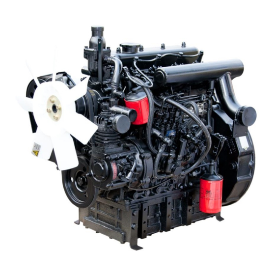
MAINTENANCE MANUAL OF ENGINE 6. Some exposed parts of engine 6.1 Left side of engine A- Fan B- Crankshaft pulley C- Fuel injection pump D- Oil pan E- Oil filter assembly F- Engine oil pressure sensor G- Flywheel cover H- Intake pipe... - Page 14 MAINTENANCE MANUAL OF ENGINE 6.2 Right side of engine A- Cylinder head cover B- Breather C- Alternator D- Starter...
-
Page 15: Chapter 3 Fuel And Engine Oil
Do not store fuel too long. If fuel has to be kept in a tank or transport vehicle for a long time, add fuel conditioner to prevent concen- tration. Contact Lovol's supplier for appropriate use and maintenance recommendations. Purchase high-quality clean fuel from the well-reputed dealers. - Page 16 MAINTENANCE MANUAL OF ENGINE 1.2 Precautions for use of fuel The biodiesel conforming to DIN51606 or diesel with equivalent performance are al- lowed. The diesel cannot be mixed with oil or other type of lubricants. Before the diesel is injected into the fuel tank, be certain that the diesel is deposited (generally above 48 hours), and then filtered to remove foreign bodies, and prevent severe...
-
Page 17: Engine Lubricating Oil
SHELL RIMULA R1 15W/40 MOBIL 15W-40 It is advisable to choose a multi-viscosity engine oil. Use of the recommended engine oil above can extend service life. You may con- tact LOVOL's supplier for details. Proper ambient temper- Engine oil designation Remarks ature 15W/40 Above -5℃... -
Page 18: Engine Coolant
MAINTENANCE MANUAL OF ENGINE 3. Engine coolant Use as cooling water the clean soft water, such as river water, rain water, snow water and tap water. Soft water contains fewer minerals. It generates little foul after heated. Less possi- bility exists that soft water causes blockage in the cooling system thus affects heat dissipa- tion. -
Page 19: Chapter 4 Position Of Product Nameplate
MAINTENANCE MANUAL OF ENGINE Chapter 4 Position of Product Nameplate 1. Information of diesel engine nameplate The nameplate of diesel engine carries the following data: manufacturer name, model, rated power/rated speed, type approval num- ber, serial number, manufacturing date, deliv- ery number, and net weight. -
Page 20: Fuel Injection Pump Nameplate
MAINTENANCE MANUAL OF ENGINE 2. Fuel injection pump nameplate Information of fuel injection pump nameplate The nameplate of fuel injection pump carries the following data: model, purchase order number, and manufacturer name. A- Position of fuel injection pump nameplate Position of fuel injection pump nameplate The nameplate is found right above the fuel injec- tion pump. -
Page 21: Position Of Alternator Nameplate
MAINTENANCE MANUAL OF ENGINE 3. Position of alternator nameplate The nameplate of alternator carries the follow- ing data: power, voltage, drawing number, tel- ephone number, and manufacturer name. A-Information of alternator nameplate Position of alternator nameplate A-Alternator nameplate... -
Page 22: Starter Nameplate
MAINTENANCE MANUAL OF ENGINE 4. Starter nameplate The nameplate of starter carries the following data: model, voltage, power, delivery number, manufac- turing date, and manufacturer name. A-Information of starter nameplate Position of starter nameplate A-Starter nameplate... -
Page 23: Air Compressor Nameplate
MAINTENANCE MANUAL OF ENGINE 5. Air compressor nameplate The nameplate of air compressor carries the fol- lowing data: model, speed, displacement, purchase order number, and manufacturer name. A-Information of air compressor nameplate Position of air compressor nameplate A- Air compressor nameplate... -
Page 24: Chapter 5 Product Features And Accessories
MAINTENANCE MANUAL OF ENGINE Chapter 5 Product Features and Accessories 1. Standard configuration Engine: 4L22BT diesel engine: 4-cylidner In-line, water-cooled Vertical, 4-stroke, direct-injection diesel engine Features of the diesel engine: Wet-type cylinder liner Natural aspiration Direct injection The standard configuration also includes: Starter motor Alternator Flame heater... -
Page 25: Configuration (Optional)
MAINTENANCE MANUAL OF ENGINE 2. Configuration (optional) Optional: air compressor assembly A- Air compressor... -
Page 26: Part Ii Dismantlement, Installation And Adjustment
MAINTENANCE MANUAL OF ENGINE Part II Dismantlement, Installation and Adjustment Chapter 1 Dismantling/installing the valve mechanism 1. Maintenance equipments and tools Note: Special tools Adjustable torque wrench 2. Torque and data 2.1. Torque requirements Measurement Item Parameters Remarks Unit Torque Bolts, cylinder head 135-150N.m Bolts, main bearing... - Page 27 MAINTENANCE MANUAL OF ENGINE 2.2 Data The data are mainly used for engine overhaul in workshop. Cylinder head Valve seat angle: Exhaust valve ------------------------------------------------------------------------------- 90° ± 20' Intake valve----------------------------------------------------------------------------------120° ± 20' +0.018 Diameter of valve guide installation hole -----------------------------------------------13 Leakage test pressure ----------------------------------------------------------------------350-400 KPa Cylinder head thickness -------------------------------------------------------------------170±...
- Page 28 MAINTENANCE MANUAL OF ENGINE Inner valve spring Installation length --------------------------------------------------------------------------- 35.3 mm Load on installation length -----------------------------------------------------------------49± 2.5 N Number of effective coil turns--------------------------------------------------------------7 Coil turn direction----------------------------------------------------------------------------Left-handed Outer valve spring Installation length ---------------------------------------------------------------------------- 37.5mm Load on installation length ------------------------------------------------------------------ 88.2± 4.4N Number of effective coil turns---------------------------------------------------------------5.25 Coil turn direction ----------------------------------------------------------------------------Right-handed Push rod...
-
Page 29: Dismantling The Valve Mechanism
MAINTENANCE MANUAL OF ENGINE 3. Dismantling the valve mechanism 3.1 Dismantling the cylinder head cover 1. Dismantle the nut (A) and gasket set (B) from the cylinder head cover (C). Loosen the cylinder head cover. A-Nut, cylinder head cover B-Gasket set C-Cylinder head cover 2. - Page 30 MAINTENANCE MANUAL OF ENGINE 3.2 Dismantling the rocker arm assembly 1. Dismantle the bolt (A) for fixing rocker arm shaft. A- Bolt for fixing rocker arm shaft 2. Dismantle the rocker arm shaft assembly (A). A-Rocker arm shaft assembly 3. Dismantle the push rod (A). A-Push rod Attention: Check the push rod for deformation or damage.
- Page 31 MAINTENANCE MANUAL OF ENGINE 4. Dismantle the bolt for fixing breather. Dismantle the breather (A). A-Breather 5. Dismantle the fuel filter (see Section 3.2, Chapter 6 of this Part). 6. Disconnect the hose of fuel-water separator (see Section 3.2, Chapter 3 of this Part)
- Page 32 MAINTENANCE MANUAL OF ENGINE 3.3 Dismantling the cylinder head assembly 1. Using a torque wrench (N.m indicated), loosen in the specified sequence the bolts (A) for fixing cyl- inder head. A- Bolt for fixing cylinder head Attention: Loosen the bolts in the diagonal se- quence.
- Page 33 MAINTENANCE MANUAL OF ENGINE 3. Remove the cylinder head. A-Cylinder head assembly Attention: Since the cylinder head is heavy, it shall be removed using a hoist, or manually by two per- sons. Place the cylinder head at a proper location, with its mating face upward to avoid scratches.
- Page 34 MAINTENANCE MANUAL OF ENGINE 3.4 Dismantling the camshaft assembly 1. Dismantle the timing gear (see Section 7.3, Chapter 7 of Part II). 2. Dismantle the camshaft (A). A-Camshaft 3.5 Dismantling the valve tappet 1. Dismantle the crankshaft assembly (see Section 3.1, Chapter 2 of Part II).
- Page 35 MAINTENANCE MANUAL OF ENGINE 3.6 Dismantling the rocker arm of valve Dismantle the snap rings (A) at both ends of the rocker arm shaft , then the locknut (G) and the valve-adjusting screw (F). Dismantle the front rocker arm seat (D), rocker arms (H and I), and rocker arm spring (E) from the rocker arm shaft.
- Page 36 MAINTENANCE MANUAL OF ENGINE 3.7 Dismantling the intake and exhaust valves Tool: Valve spring compression tool Using the valve spring compression tool and the corresponding attachment, compress the valve spring to remove the valve split cone. Dismantle the valve split cone (A). Take out the upper valve spring retainer (B), outer valve spring (C), inner valve spring (D), valve stem oil seal seat (E), valve guide (F), intake valve seat (G), exhaust...
-
Page 37: Installing The Valve Mechanism
MAINTENANCE MANUAL OF ENGINE 4. Installing the valve mechanism 4.1 Installing the valve tappet 1. Install the cylinder liner (see Section 4.1, Chapter 2 of Part II). Keep its mating face clean before installing the valve tappet. 2. Apply lubricating oil to the valve tappet. A-Valve tappet 3. - Page 38 MAINTENANCE MANUAL OF ENGINE 4.2 Installing the camshaft 1. Install the camshaft (A). A-Camshaft Before installing the camshaft, check that its ma- chined surfaces are free of dirt and scratches, and then apply clean lubricating oil to these surfaces. 2. Tighten the bolt (A) for fixing camshaft. A- Bolt...
- Page 39 MAINTENANCE MANUAL OF ENGINE 4.3 Installing the intake and exhaust valves Using the valve spring compression tool and the corresponding attachment, compress the valve spring to remove the valve split cone. Install the intake and exhaust valves in place, refer- ring to the match marks made when removing them.
- Page 40 MAINTENANCE MANUAL OF ENGINE Installing the valve spring Replacement of valve spring Special tools: Valve spring compression tool Screw stud attachment Alignment screw attachment Attention: The following description is for the re- placement of valve springs of a single cylinder. Warning: Wear protective goggles when replacing valve springs.
- Page 41 MAINTENANCE MANUAL OF ENGINE 4.4 Correcting the valve seat Special tools: Reamer for intake valve seat Reamer for exhaust valve seat Guide bar, used along with the reamer Handle set used along with the reamer 1. Do not move the valve seat before installing the new valve guide.
- Page 42 MAINTENANCE MANUAL OF ENGINE 4.5 Measuring the clearance between valve stem and guide Checking the valve guide for wear: The maximum permissible clearance between in- take valve stem and guide is 0.13 mm, and that be- tween exhaust valve stem and guide is 0.15mm. If the clearance exceeds the limit after installing a new valve stem, it is required to install also a new valve guide.
- Page 43 MAINTENANCE MANUAL OF ENGINE 4.6 Installing the cylinder head Clean the mating face of engine block. Check that the cylinder head gasket is in the correct direction. 1. Install the cylinder head gasket (A). A-Cylinder head gasket 2. Install the cylinder head assembly (A). A-Cylinder head assembly Attention Before closing the cylinder head, align its two...
- Page 44 MAINTENANCE MANUAL OF ENGINE 3. Insert the bolts (A) for fixing cylinder head. Pre-tighten them in the specified sequence. A-Bolt for cylinder head 4. Tighten the bolts (A) again in the specified se- quence to the specified torque. A- Bolt tightening diagram Torque --------135 to 150N.m Attention: First pre-tighten the bolts, and then tighten them to...
- Page 45 MAINTENANCE MANUAL OF ENGINE 4.7 Installing the rocker arm assembly Check the push rod for deformation. If any, replace it with a new one. 1. Install the push rod (A). A-Push rod 2. Install the rocker arm shaft (A). A-Rocker arm shaft...
- Page 46 MAINTENANCE MANUAL OF ENGINE 3. Tighten the bolt (A) for fixing rocker arm shaft. A- Bolt for fixing rocker arm shaft Tightening torque-----------------21-25N.m Inspection Check the rocker arm assembly for wear and other damage. Check the clearance between rocker arm shaft and bushing.
- Page 47 MAINTENANCE MANUAL OF ENGINE 4.8 Adjusting the valve clearance Tool: Open-end wrench, flat-tip screwdriver, feeler gauge Firing order for a 3-cylinder engine: 1-3-2 Valve clearance adjustment rule: When the piston of cylinder 1 comes to the top dead center, valve clearance can be adjusted for both the intake and exhaust valves of cylinder 1, exhaust valve of cyl- inder 3, and intake valve of cylinder 2.
- Page 48 MAINTENANCE MANUAL OF ENGINE 4.9 Installing the cylinder head cover First check the gasket of cylinder head cover for damage. If any, replace it with a new one. 1. Install the gasket and cylinder head cover. A-Gasket of cylinder head cover B-Cylinder head cover 2.
-
Page 49: Chapter 2 Dismantling/Installing The Crank-Link Mechanism
MAINTENANCE MANUAL OF ENGINE Chapter 2 Dismantling/installing the crank-link mechanism 1. Maintenance equipments and tools Special tools: 16/19 Open-end wrench, 13 socket wrench, 18 socket wrench, digital torque wrench, adjustable torque wrench 2. Torque and data 2.1. Torque requirements Measurement Item Parameters Remarks... - Page 50 MAINTENANCE MANUAL OF ENGINE Connecting rod-naturally aspirated engine Type-----------------------------------------------------------------------H-section, square end Positioning of bearing cap and connecting rod---------------------Saw-tooth type +0.019 Diameter of hole at big end of connecting rod ---------------------Φ54 +0.025 Diameter of hole at small end of connecting rod-------------------Φ31 Center distance--------------------------------------------------------- 145±...
-
Page 51: Dismantling The Crank-Link Mechanism
MAINTENANCE MANUAL OF ENGINE 3. Dismantling the crank-link mechanism 3.1 Dismantling the crankshaft 1. Dismantle high pressure fuel pipe accessories (See Section 3, Chapter 6 of this Part for the de- tails). 2. Dismantle the gear chamber (See Section 7, Chapter 7 of this Part for the details). - Page 52 MAINTENANCE MANUAL OF ENGINE 7. Dismantle the main bearing cap bolt A succes- sively. A-Main bearing cap bolt 8. Dismantle the main bearing cap A. A-Main bearing cap 9. Dismantle main bearing cap A and main bearing shell B, which shall be placed neatly. A-Main bearing cap B-Main bearing shell Attention:...
- Page 53 MAINTENANCE MANUAL OF ENGINE 10. Take down the crankshaft A. A-Crankshaft Attention If suitable lifting tools are not equipped, two per- sons shall cooperate to lift up the crankshaft togeth-...
- Page 54 MAINTENANCE MANUAL OF ENGINE 3.2 Dismantling the piston connecting rod assembly Attention: Clear the carbon deposition on upper cylinder head. If it is not cleared or not cleared fully, it may cause damage to the piston ring. 1. Push out the piston connecting rod assembly from one side of crankshaft by stick or rubber rod.
- Page 55 MAINTENANCE MANUAL OF ENGINE 3.3 Dismantling the cylinder liner Special tools: Tools for dismantling/ replacing the cylinder liner Several cylinder liners shall be dismantled, or pressing machine shall be used when the cylinder linear for installation and production is too tight; when dismantling single cylinder liner, or when crankshaft is kept in installation position, manual operating tool shall be equipped.
- Page 56 MAINTENANCE MANUAL OF ENGINE 3.4 Dismantling the piston ring and connecting Dismantle piston ring with suitable piston ring ex- pander and store the piston ring with corresponding piston. Dismantle piston ring assembly A and check ring B; take out piston pin F and take out connecting rod body B from piston C.
-
Page 57: Installing The Crank-Link Mechanism
MAINTENANCE MANUAL OF ENGINE 4. Installing the crank-link mechanism 4.1 Installing the cylinder liner Attention: Damaged or worn cylinder liner must be scrapped. When replacing cylinder liner, piston ring must be replaced simultaneously. Cylinder liner needs not to be replaced under fol- lowing conditions: ◆Honing lines are clear and visible. - Page 58 MAINTENANCE MANUAL OF ENGINE Attention: Do not knock on cylinder liner by ham- mer. 1. Completely clean the cylinder liner mounting bore. 2. Completely clean the outside surface of cylinder liner by safety solvent. 3. Insert the cylinder liner E into original mounting bore.
- Page 59 MAINTENANCE MANUAL OF ENGINE 4.2 Installing the crankshaft 1. Install the cylinder liner (See Section 3 of this Chapter for details) 2. Install the valve tappet (See Chapter 4.1, Chapter 1, Part II). Attention: Before installation, make sure that original mount- ing bore and bearing bush surface are clean without foreign substance, or it will influence the fit preci- sion.
- Page 60 MAINTENANCE MANUAL OF ENGINE 5. Install crankshaft thrust plate. A-Thrust plate Attention: When installing thrust plate, pay attention to make the side with oil groove face the crankshaft. When installing bearing shell, the locating slot of upper bearing shell on bearing cap shall be on the same side with the locating slot of bearing shell of origi- nal mounting bore.
- Page 61 MAINTENANCE MANUAL OF ENGINE 8. Install the main bearing cap A. A-Main bearing cap After installation, refuel clean lubricating oil in bearing shell. 9. Install the main bearing cap bolt A. A- Bolt 10. Fasten the bolt A. Attention: When locking the cap, it shall be fastened symmet- rically and evenly.
- Page 62 MAINTENANCE MANUAL OF ENGINE 11. Installation of gear chamber (See Section 7.3, Chapter 7 of Part II for details). 12. Install crankshaft pulley A. A-Crankshaft pulley Attention When installing crankshaft pulley, copper hammer cannot be directly used for knocking. 13. Install the set bolt. A- Bolt Bolt torque-----160-170N.m...
- Page 63 MAINTENANCE MANUAL OF ENGINE 4.3 Installing the piston connecting rod assembly 4.3.1 Installing the piston ring First gaseous ring (opening clearance: 0.35-0.5mm) Second gaseous ring (opening clearance: 0.25-0.45mm) ring component (opening clearance: 0.25-0.45mm) Attention: detect the opening clearance of piston ring in standard cylinder liner.
- Page 64 MAINTENANCE MANUAL OF ENGINE 3. Install the oil ring and gaseous ring onto the pis- ton. A-Piston Attention ◆Opening position of oil ring shall be staggered by 180° with oil ring spring interface. ◆The surface which is printed with manufacturer logo on gaseous ring shall face the piston top.
- Page 65 MAINTENANCE MANUAL OF ENGINE 4.3.2 Installing the connecting rod bushing Inspection: ◆Check whether connecting rod is deformed. Note: Big end of connecting rod and small end bearing bore must be flat and parallel. Check the two sides of connecting rod axis and the result shall not exceed +/-0.25mm limit.
- Page 66 MAINTENANCE MANUAL OF ENGINE 4.3.3 Installing the piston pin Inspection: ◆Check the fit of piston pin and small end bushing and check whether piston pin is worn. Before installation, make sure that piston pin and small end of connecting rod are clean and lubricate by clean engine lubricating oil.
- Page 67 MAINTENANCE MANUAL OF ENGINE 3. Install piston pin to connect connecting rod with piston. A-Connecting rod B-Piston pin C-Piston Attention: When piston is assembling with connecting rod, the direction shall not be reserve. Pay attention to the marking on piston and connecting rod body to as- semble by marking direction.
- Page 68 MAINTENANCE MANUAL OF ENGINE 4.4 Install piston connecting rod assembly into cylinder liner Confirm the installation direction of piston and in- stall the piston into cylinder liner. When installing, pay attention that the "marking" direction at top face of piston shall face the front end of engine, meanwhile make sure that the open- ing position of three rings are staggered by 120°...
- Page 69 MAINTENANCE MANUAL OF ENGINE 3. Install the piston. A-Piston B-Special tool Attention: Somebody shall knock the piston by stick or rubber stick on the upper end and somebody shall watch the swing connecting rod at lower end to avoid connecting rod bumping on crankshaft journal. Clean the cylinder liner before installation and coat clean lubricating oil.
-
Page 70: Chapter 3 Cooling System
MAINTENANCE MANUAL OF ENGINE Chapter 3 Cooling system 1. Maintenance equipments and tools Note: Special tools: 16/19 open wrench 8 socket wrench 13 socket wrench Digital torque wrench 2. Torque requirements Measurement Item Parameters Remarks Unit Bolts, connecting water pump to cylinder head and Torque 25N·... -
Page 71: Dismantling The Cooling Part
MAINTENANCE MANUAL OF ENGINE 3. Dismantling the cooling part 3.1 Dismantle the attaching clamp of water outlet switch Before dismantling, drain the cooling water. 1. Dismantle the attaching clamp of water outlet switch. A-Attaching clamp of water outlet switch... - Page 72 MAINTENANCE MANUAL OF ENGINE 3.2 Dismantle the hose of fuel-water separator 1. Loosen the jacket A A-Jacket 2. Disconnect the hose of fuel-water separator A A-Hose of fuel-water separator...
- Page 73 MAINTENANCE MANUAL OF ENGINE 3.3 Dismantle fan components 1. Dismantle fan set bolt A A-Set bolt 2. Dismantle fan A A-Fan 3. Dismantle fan belt A-Fan belt...
- Page 74 MAINTENANCE MANUAL OF ENGINE 3.4 Dismantle water pump components 1. Dismantle water pump set bolt A A-Set bolt 2. Take down water pump cover A A-Water pump cover 3. Take down water pump assembly A A-Water pump assembly...
- Page 75 MAINTENANCE MANUAL OF ENGINE 3.5 Dismantle the fan and pulley Attention: Before disassembling water pump component, firstly drain the water in radiator. 1. Dismantle belt A and belt B. A- Belt from fan to generator. B- Belt from crankshaft to fan 2.
- Page 76 MAINTENANCE MANUAL OF ENGINE 3.6 Dismantle the water pump assembly 1. Dismantle bolt A, take out thermostat D. 2. Dismantle bolt F, dismantle water pump assembly, take out gasket E, cushion block G and gasket H. A- Bolt B-Thermostat housing; C-Thermostat housing gasket;...
-
Page 77: Assembling The Cooling Part
MAINTENANCE MANUAL OF ENGINE 4. Assembling the cooling part 4.1 Installing the water pump assembly Clean the surface of cylinder liner and cooling liq- uid and lubricating oil passage; water jacket can be cleaned by special solvent, which shall follow the instruction of manufacture when using. - Page 78 MAINTENANCE MANUAL OF ENGINE 4.2 Installing the water pump components 1. Install water pump gasket A A-Water pump gasket 2. Install water pump component A A-Water pump component 3. Fasten water pump set bolt A A- Bolt...
- Page 79 MAINTENANCE MANUAL OF ENGINE 4.3 Installing the hose of fuel-water separator 1. See Section 4.2 of this chapter for installation of water pump components. 2. Install the hose of fuel-water separator and fas- ten. A-Hose of fuel-water separator...
- Page 80 MAINTENANCE MANUAL OF ENGINE 4.4. Installing the fan 1. Install alternator components (See Section 3, Chapter 5 of this Part). 2. Install fan A and fasten the bolt. A-Fan 3. Install belt A A-Belt Belt tension ---98N...
-
Page 81: Chapter 4 Lubricating System
MAINTENANCE MANUAL OF ENGINE Chapter 4 Lubricating System 1. Maintenance equipments and tools Note: Introductions for special tools Open-end wrench or offset ring wrench 2. Torque requirements Measurement Item Parameters Remarks Unit The engine oil pump is assembled onto the engine Torque 25N.m body... -
Page 82: Dismantling/Installing The Oil Pan Parts
MAINTENANCE MANUAL OF ENGINE 3. Dismantling/installing the oil pan parts 3.1 Dismantling the oil pan parts 1. Empty the oil, and overturn the engine. Disman- tle the set bolts A of the oil pan part. A- Bolt 2. Dismantle the oil pan part A A-Oil pan part Attention: Pay attention to personal safety during dismantling because the oil pan is heavy. - Page 83 MAINTENANCE MANUAL OF ENGINE 3.2 Installing the oil pan parts 1. Install the oil pan gasket A A-Oil pan gasket Attention Install a new oil pan gasket. 2. Install the oil pump parts (see Section 4.2 in this chapter) 3. Install the oil pan. A-Oil pan 4.
-
Page 84: Dismantling/Installing The Oil Pump Parts
MAINTENANCE MANUAL OF ENGINE 4. Dismantling/installing the oil pump parts 4.1 Dismantling the oil pump parts 1. Dismantle the set bolts of the oil pump. A- Bolt 2. Dismantle the oil pump parts A. A-Oil pump part... - Page 85 MAINTENANCE MANUAL OF ENGINE 4.2 Installing the oil pump parts 1. Install the oil pump assembly A-Oil pump assembly 2. Tighten the bolts A of the oil pump. A- Bolt...
-
Page 86: Chapter 5 Electric System
MAINTENANCE MANUAL OF ENGINE Chapter 5 Electric system 1. Maintenance equipments and tools Introductions for special tools Sleeve 2. Torque requirements Measurement Item Parameters Remarks Unit Connection between the Torque 80N.m starter and flywheel cover... -
Page 87: Dismantling/Installing The Alternator Assembly
MAINTENANCE MANUAL OF ENGINE 3. Dismantling/installing the alternator assembly 3.1 Dismantling the alternator assembly 1. Dismantle the nuts A for the adjusting bracket of the alternator. A-Nut 2. Dismantle the adjusting bracket A of the alterna- tor. A-Alternator bracket 3. Dismantle the alternator A. A-Alternator assembly... - Page 88 MAINTENANCE MANUAL OF ENGINE 3.2 Installing the alternator 1. Install the alternator assembly A. A-Alternator 2. For installation of the fan belt, see Section 4.3, Chapter 3, Part II. 3. Tighten the bolts A for the alternator. A- Bolt Attention The alternator bolts can be tightened unless and until the belt is installed properly.
-
Page 89: Dismantling The Alternator Subassembly
MAINTENANCE MANUAL OF ENGINE 4. Dismantling the alternator subassembly 4.1 Inspecting the whole machine prior to dismantling 1. The resistance between terminal “F” and “-” is 4~8Ω. If the resistance is too small, the possible cause is that the field coil is shorted or the insulat- ing spacer is damaged;... -
Page 90: Dismantling/Installing The Starter
MAINTENANCE MANUAL OF ENGINE 5. Dismantling/installing the starter 5.1 Dismantling the starter 1. Dismantle the starter bolt A A-Set bolt B-Starter assembly Attention: Hold the starter by hands during disman- tling, and pay attention to personal safety. 5.2 Installing the starter 1. -
Page 91: Chapter 6 Fuel Supply System
MAINTENANCE MANUAL OF ENGINE Chapter 6 Fuel supply system 1. Maintenance equipments and tools Note: Introductions for special tools Sleeve 2. Torque requirements Measurement Item Parameters Remarks Unit Connection between the fuel injection pump and Torque 70N.m the gear chamber... -
Page 92: Dismantling The Fuel Supply System
MAINTENANCE MANUAL OF ENGINE 3. Dismantling the fuel supply system 3.1 Dismantling the accessories for the high pressure fuel pipe Prior to dismantling, disconnect the fuel inlet pipe. 1. Dismantle the fuel return pipe part A, and the fuel pipe B from the fuel filter to the fuel injection pump. - Page 93 MAINTENANCE MANUAL OF ENGINE 4. Dismantle the bolt, and remove the fuel pipe A from the fuel filter to the fuel injection pump. A-Hollow bolt B-Fuel pipe from the fuel filter to the fuel injection pump 5. Dismantle the remaining fuel pipeline A. A-Other pipeline...
- Page 94 MAINTENANCE MANUAL OF ENGINE 3.2 Dismantling the fuel filter assembly 1. Dismantle the set bolt A for the fuel filter, and remove the fuel filter assembly B. A-Bolt B-Fuel filter assembly 3.3 Dismantling the fuel injector assembly 1. Dismantle the fuel injector assembly. A-Fuel injector...
- Page 95 MAINTENANCE MANUAL OF ENGINE 3.4 Dismantling the fuel injection pump assem- Attention: Prior to removal of the fuel injection pump and if no maintenance is required for the fuel injection pump, it is able to make a mark on the fuel injection pump and timing gear chamber, respectively, to fa- cilitate subsequent installation.
-
Page 96: Assembling The Fuel Supply System
MAINTENANCE MANUAL OF ENGINE 4. Assembling the fuel supply system 4.1 Installing the fuel injector 1. Install the fuel injector parts. A-Fuel injector Attention Prior to installation, clean out the carbon deposit in the fuel injector; if unaccepted, replace the whole fuel injector assembly. - Page 97 MAINTENANCE MANUAL OF ENGINE 4.3 Installing the fuel filter 1. Install the fuel filter assembly, and connect the pipeline. A-Fuel filter assembly B-Fuel pipeline Use of an genuine filter is very important, and use of a wrong filter element will result in damage to the fuel injection pump.
-
Page 98: Chapter 7 Dismantling/Installing And Adjusting The Accessories
MAINTENANCE MANUAL OF ENGINE Chapter 7 Dismantling/installing and adjusting the accessories 1. Data and dimension Camshaft gear Number of teeth-------------------------------------------------------------------------------------------- 48 teeth +0.021 Bore diameter------------------------------------------------------------------------------------------------Φ30 +0.021 Outer diameter of camshaft hub---------------------------------------------------------------------------Φ30 +0.008 Clearance fit between gear and hub------------------------------------------------------------------ (-0.021)-0.013 mm Fuel injection pump gear Number of teeth-------------------------------------------------------------------------------------------- 48 teeth +0.035... -
Page 99: Dismantling/Installing The Intake Pipe
MAINTENANCE MANUAL OF ENGINE 2. Dismantling/installing the intake pipe 2.1 Dismantling the intake pipe 1. Loosen the fixing nut for the intake pipe, and dismantle the intake pipe A. A-Intake pipe assembly 2. Remove the gasket A. A-Intake pipe gasket... - Page 100 MAINTENANCE MANUAL OF ENGINE 2.2 Installing the intake pipe 1. Install the gasket A. A-Intake pipe gasket Attention: Prior to installation, replace it with a new one. 2. Install the intake pipe A, and tighten it. A-Intake pipe assembly...
-
Page 101: Dismantling/Installing The Exhaust Pipe
MAINTENANCE MANUAL OF ENGINE 3. Dismantling/installing the exhaust pipe 3.1 Dismantling the exhaust pipe. 1. Dismantle the nut A. A-Locknut for the exhaust pipe B-Exhaust pipe assembly 2. Remove the exhaust pipe gasket A. A-Exhaust pipe gasket... - Page 102 MAINTENANCE MANUAL OF ENGINE 3.2 Installing the exhaust pipe 1. Install the exhaust pipe gasket A. A-Exhaust pipe gasket Attention: Prior to installation, replace it with a new one. 2. Install the exhaust pipe A, and install and tighten the nut B. A-Exhaust pipe assembly B-Nut...
-
Page 103: Dismantling/Installing The Gear Chamber
MAINTENANCE MANUAL OF ENGINE 4. Dismantling/installing the gear chamber 4.1 Dismantling the gear chamber 1. Dismantle the alternator assembly (Refer to Sec- tion 3.1, Chapter 5, Part II). 2. Dismantle the fan parts (Refer to Section 3.4, Chapter 5, Part II). 3. - Page 104 MAINTENANCE MANUAL OF ENGINE 7. Dismantle the bolts for the cover of the timing gear chamber. A- Bolt 8. Dismantle the cover A of the timing gear cham- ber. A-Cover of the timing gear chamber 9. Dismantle the idle gear bolt A. A- Bolt 10.
- Page 105 MAINTENANCE MANUAL OF ENGINE 11. Dismantle the starter parts (See Section 4.1, Chapter 5 of this Part). 12. For dismantling of the flywheel, see Section 7.4, Chapter 7, Part II. 13. Dismantle the camshaft part A. A-Camshaft part 14. Dismantle the advancer part A with a special tool.
- Page 106 MAINTENANCE MANUAL OF ENGINE 16. Dismantle the set bolt A for the timing gear chamber. A- Bolt 17. Dismantle the timing gear chamber A and fuel injection pump B. A-Timing gear chamber B-Fuel injection pump Attention: The timing gear chamber is connected with the fuel injection pump, and they are not sepa- rated.
- Page 107 MAINTENANCE MANUAL OF ENGINE 4.2 Installing the gear chamber 1. Install the crankshaft (For details see Section 4.2, Chapter 2 of this Part). 2. Install the idler shaft A. A-Idler shaft 3. Install the gasket A. A-Gear chamber gasket Attention During installation, replace it with a new one.
- Page 108 MAINTENANCE MANUAL OF ENGINE 5. Install the camshaft part A. A-Camshaft part Attention: Prior to installation, ensure that individu- al surfaces are clean, and free of scratches, and ap- plied with clean lubricating oil. Prior to installation of the camshaft, it is required to install the tappet.
- Page 109 MAINTENANCE MANUAL OF ENGINE 8. Install the intermediate idle gear. A-Intermediate idle gear B-Align marking Attention: During installation of the intermediate idle gear, it is required to align the three timing marks with corresponding timing marks of the high pressure fuel pump gear, camshaft gear, crankshaft timing gear, and finally tighten the bolts.
- Page 110 MAINTENANCE MANUAL OF ENGINE 10. Install the gasket for the timing gear chamber, and timing gear chamber cover. A-Gasket for the timing gear chamber cover B-Timing gear chamber cover 11. Tighten the bolts for the cover of the timing gear chamber.
-
Page 111: Dismantling/Installing The Flywheel Parts
MAINTENANCE MANUAL OF ENGINE 5. Dismantling/installing the flywheel parts 5.1 Dismantling the flywheel parts 1. Dismantle the bolt A and lockplate B. A-Flywheel bolt B-Lockplate 2. Remove the flywheel part A. A-Flywheel part Pay attention to personal safety. 3. Dismantle the bolt A, and remove the flywheel cover B. - Page 112 MAINTENANCE MANUAL OF ENGINE 5.2 Installing the flywheel parts Attention During installation of the flywheel cover, first apply clean lubricating oil at rear end of the crankshaft. A-Rear end of the crankshaft 1. Install the dowel pin A, and install the gasket B. A-Dowel pin B-Flywheel cover gasket Attention: During installation, replace the gasket...
- Page 113 MAINTENANCE MANUAL OF ENGINE 3. Install the flywheel A, install the lockplate B and bolt C. A-Flywheel B-Lockplate C-Bolt Attention: Prior to installation of the flywheel, in- spect whether the dowel pin at the end of the crankshaft is lost. 4.
-
Page 114: Part Iii Inspection, Adjustment, Fault Diagnosis And Troubleshooting
MAINTENANCE MANUAL OF ENGINE Part III Inspection, Adjustment, Fault Diagnosis and Troubleshooting Chapter 1 Dynamic Inspection 1. Overview According to operating time and condition of the engine, inspect the engine oil consumption on a regular basis or from time to time, and replenish engine oil in time. -
Page 115: Inspecting Engine Oil Level
MAINTENANCE MANUAL OF ENGINE 2. Inspecting engine oil level Inspection conditions: ◆The machine is stopped at a level ground. ◆The shift lever is at neutral position. ◆The ignition lock is off. ◆The parking brake is pulled tightly. ◆Five minutes after the engine stops. Inspection steps: ◆Clean surrounding of the oil dipstick. -
Page 116: Inspecting The Coolant Level And Status
MAINTENANCE MANUAL OF ENGINE 3. Inspecting the coolant level and status Inspection conditions: ◆The machine is stopped at a level ground. ◆The ignition lock is off. ◆The radiator cover is not overheated. ◆The parking brake is pulled tightly. Inspection steps: ◆Clean the surroundings of the radiator cover. -
Page 117: Inspecting The Fan And Belt
MAINTENANCE MANUAL OF ENGINE 4. Inspecting the fan and belt 1. Inspect the water pump belt Inspect whether the water pump belt is cracked, cut, deformed and worn and torn. Whenever necessary, it is required to replace the belt and inspect its ten- sion. -
Page 118: Inspecting The Fuel System
MAINTENANCE MANUAL OF ENGINE 5. Inspecting the fuel system The fuel system, through the fuel delivery pump, delivers the fuel into the high pressure fuel pump from the fuel tank and via the fuel filter and low pressure fuel line, and then the fuel is pumped by the high pressure pump into the high pressure pipe and is injected into the cylinder (at pressure of 21-23MPa) by the fuel injector, then compressed... -
Page 119: Inspecting The Air Intake And Exhaust System
MAINTENANCE MANUAL OF ENGINE 6. Inspecting the air intake and exhaust system 1. The air flows through the air filter, enters the air intake manifold via the heater, and goes into the port on the cylinder head from the air intake mani- fold, and is pressurized into the cylinder after being sucked into the air intake valve, then compressed and fired in the cylinder. -
Page 120: Inspecting The Electric System
MAINTENANCE MANUAL OF ENGINE 7. Inspecting the electric system There may be explosive gas escaped from the battery. In order to prevent serious personal injury, the engine compartment has to be ventilated well before conducting the work. First, always enable the cathode (-) cable of the battery to be disconnected, and connect the cathode (-) cable. -
Page 121: Chapter 2 Operating Principle
MAINTENANCE MANUAL OF ENGINE Chapter 2 Operating principle 1. Valve mechanism 1.1 Function of valve mechanism The cylinder head is used to enclose the top of the cylinder, and works with the cylinder and piston to jointly form the combustion chamber and work- ing chamber. - Page 122 MAINTENANCE MANUAL OF ENGINE 1.2 Valve timing The valve timing means the actual opening and closing time of the air intake valve and exhaust Upper dead point valve, which is represented by a doughnut chart for the crank angle in relation to the crank position of Exhaust valve the upper and lower dead points.
-
Page 123: Crank-Link Mechanism
MAINTENANCE MANUAL OF ENGINE 2. Crank-link mechanism 2.1. Operating principle Function: The crank-link mechanism is the transmission mechanism used to realize the duty cycle of the combustion engine and complete energy conversion, as well as transmit the power and change the mode of motion. - Page 124 MAINTENANCE MANUAL OF ENGINE 2.2 Introduction for components Composition: Crankshaft: Convert the gas pressure transmitted from the Engine body components: cylinder block, cylinder piston connecting rod component to the output liner, cylinder head, cylinder gasket and oil sump torque. Then, it is used to drive the valve mecha- and etc.
-
Page 125: Lubricating System
MAINTENANCE MANUAL OF ENGINE 3. Lubricating System During operation of the engine, the lubricating sys- tem is functioned to continuously deliver abundant clean lubricating oil to friction surfaces of all driv- ing parts, form an oil film between the friction sur- faces to realize fluid friction, decrease friction re- sistance, reduce power consumption and lighten wear, improving engine operating reliability and... -
Page 126: Fuel Supply System
MAINTENANCE MANUAL OF ENGINE 4. Fuel supply system 4.1 Theoretical information System function: The fuel system is mainly used to deliver the fuel into the high pressure fuel pump from the fuel tank and via diesel filter and pipeline with help of the fuel delivery pump, and then the fuel is pumped from the high pressure pump, flows through the high pressure fuel pipe, and is injected to the cylinder by the fuel injector (at... -
Page 127: Cooling System
MAINTENANCE MANUAL OF ENGINE 5. Cooling system The lubricant nipple of the water pump should Function: be injected with grease on a regular basis. Usually, The engine can be kept within an appropriate the grease should be replenished every about 200 temperature range in all conditions. -
Page 128: Electric System
MAINTENANCE MANUAL OF ENGINE 6. Electric system 6.1 Introductions for starter 6.1.1 Structural principle of the starter A-One-way clutch B-Fork seat C-Fork shaft D-Fork E-Hold-down ring F-Gasket G-Water proof rubber sleeve H-Rubber gasket I-Electromagnetic switch J-Armature assembly K-Stator assembly L-Carbon brush holder assembly M-Rear cover N-Water proof rubber washer O-Planetary gear ring cover P-Rubber gasket Q-Planetary gear ring... - Page 129 MAINTENANCE MANUAL OF ENGINE 6.1.2 Use and maintenance of the starter 1. Precautions for use of the starter ◆Frequently inspect connecting condition of in- dividual parts and tightness of the cables. ◆Remove oxides on the cables and terminals, clean the dust and oil stains deposited on the exter- nal of the starter.
- Page 130 MAINTENANCE MANUAL OF ENGINE 6.2 Structural principle of the alternator Introductions for the alternator 2. Construction of the alternator-Stator as- The alternator is a three-phase alternator. Its prin- sembly ciple is to convert the mechanical energy into electric energy through the rotating magnetic field. Function of the stator components: To produce a Then, it delivers electric power to electric equip- three-phase alternating current.
- Page 131 MAINTENANCE MANUAL OF ENGINE whose negative brush (e) of the field winding is 3. Construction of the alternator--Silicon recti- directly grounded to the alternator (directly con- fier nected with the housing) Externally grounded alternator: It is an alternator Function of the rectifier: Converts the three-phase whose two brushes of the field winding are insu- alternating current of the stator winding into direct lated from the housing.
- Page 132 MAINTENANCE MANUAL OF ENGINE winding), the negative tube at the phase with Working principle of the three-phase alterna- minimum voltage breaks over at certain instant, but there are two closed tubes at the same time, of 1. Power generation principle which one is a positive tube, the other one is neg- Electromagnetic induction phenomenon: ative tube.
- Page 133 MAINTENANCE MANUAL OF ENGINE tion power generation. This is the main cause that the alternator has excellent low-rate charging per- formance. Usually, the separate excitation is switched to self-excitation after the alternator speed is up to 1000r/min. Self-excitation As the alternator speed increases, the electromo- tive force of the alternator gradually increases and can be output (usually at the time when the engine speed is up to idling speed).
- Page 134 MAINTENANCE MANUAL OF ENGINE Operating principle: volume, high reliability, long service life and a. Non-charging state: With the power switch small radio interference and etc., it acts as an ex- turned on, the excitation current flows as follows: ternal regulator, which is widely substituted for battery +--k---charging indicator lamp-regulator the electromagnetic vibration regulator.
-
Page 135: Chapter 3 Inspection And Adjustment
MAINTENANCE MANUAL OF ENGINE Chapter 3 Inspection and adjustment 1. Inspecting valve clearance (mm) Cause: taken account of. The compressive force of the cylinder is insufficient, 1. The piston ring is deposited with carbon, jammed and there is black smoke and abnormal sound dur- or worn. -
Page 136: Inspecting Cylinder Pressure
MAINTENANCE MANUAL OF ENGINE 2. Inspecting cylinder pressure Cause: It is used to inspect whether there is white smoke resulting from insufficient compressive force of the cylinder. Equipment: Pressure tester, open-end spanner Connection: The sensor is inserted into the glow plug hole, and then a pressure tester is connected. -
Page 137: Inspecting The Engine Oil Pressure
MAINTENANCE MANUAL OF ENGINE 3. Inspecting the engine oil pressure Cause: To confirm whether the bearing or lubricating system component is worn. Equipment: Pressure indicator assembly Hose assembly Temperature indicator Connection: 1. Dismantle the engine oil pressure sensor Note: The thread is taper pipe thread 1/8, and it is required that the pressure range is (0—700)kPa ((0 —6.9) bar or (0—100) psi) for special fittings and hose connections. - Page 138 MAINTENANCE MANUAL OF ENGINE Specification Engine oil temperature (engine speed of 825rpm) 93° C (220F) Engine oil temperature (engine speed of 2500rpm) 105° C (220F) Minimum pressure of the engine oil (engine speed of 825rpm) 100 kPa (1 bar or 15 psi) Minimum pressure of the engine oil (engine speed of 2500rpm) 277—483 kPa (2.77—4.83 bar or 40—70 psi)
-
Page 139: Inspecting Fuel Injection Pump Timing
MAINTENANCE MANUAL OF ENGINE 4. Inspecting fuel injection pump timing Cause: High fuel consumption rate, poor power perfor- mance and black smoke. Equipment: Special socket or open-end spanner Testing steps: 1. Remove the air in the fuel system, enable the crankshaft to be reciprocated to get the oil injection pump fully filled with diesel fuel, and dismantle the 1st high pressure oil hose to blow out the residual... -
Page 140: Calibration Of The Fuel Injection Pump
MAINTENANCE MANUAL OF ENGINE 5. Calibration of the fuel injection pump Cause: The fuel supply to the individual cylinders is non-uniform, and the fuel injection pressure is in- sufficient. Equipment: Fuel pump test bench Testing steps: 1. Install the fuel injection pump onto the test bench, connect the standard fuel injector, and then turn the fuel pump to pump fuel. -
Page 141: Inspecting Atomization By The Fuel Injector
MAINTENANCE MANUAL OF ENGINE 6. Inspecting atomization by the fuel injector Cause: Black smoke from the diesel engine, insufficient power, increase in fuel consumption and other trou- bles. Equipment: Pressure tester, open-end spanner , fuel injector test bench Test steps and adjustment: 1. -
Page 142: Chapter 4 Fault Analysis And Troubleshooting
MAINTENANCE MANUAL OF ENGINE Chapter 4 Fault analysis and troubleshooting 1. White smoke Inspection po- Steps Fault causes Troubleshooting sition The possible cause is that the fuel injector pressure is lower Repair or change the fuel injector (Re- Fuel injector than 23MPa, the fuel is atom- fer to Section 3, Chapter 6, Part II) ized poorly, or there is fuel... -
Page 143: Black Smoke Or Grey Smoke
MAINTENANCE MANUAL OF ENGINE 3. Black smoke or grey smoke Inspection Steps Fault causes Troubleshooting position The fuel injector or the injector nozzle is damaged or blocked, resulting in poor Repair or replace (Refer to Sec- Fuel injector atomization and insufficient combus- tion 6, Chapter 3 of this Part) tion. -
Page 144: Air Intake Obstructed
MAINTENANCE MANUAL OF ENGINE 5. Air intake obstructed Inspection Steps Fault causes Troubleshooting position The filter element is damaged, and the Replace the filter element or clean Air filter air filter is blocked. the air filter. Air intake The air intake pipeline is blocked. Clean the air intake pipeline. -
Page 145: Abnormal Sound From The Diesel Engine
MAINTENANCE MANUAL OF ENGINE 7. Abnormal sound from the diesel engine Inspection Steps Fault causes Troubleshooting position The fuel supply advance angle is too Fuel supply Adjust the fuel supply advance big, and there is rhythmic metallic advance angle angle to 16° ± 1° knocking sound. -
Page 146: The Engine Cannot Be Operated Normally Or Flames Out Frequently
MAINTENANCE MANUAL OF ENGINE 8. The engine cannot be operated normally or flames out frequently Inspection Steps Fault causes Troubleshooting position The air passage is obstructed, resulting Fuel tank cap in negative pressure built up in the fuel Clean or replace tank. -
Page 147: Low Power
MAINTENANCE MANUAL OF ENGINE 9. Low power Inspection Steps Fault causes Troubleshooting position Diesel filter or The fuel inlet/outlet pipe or strainer Clean or replace is blocked. fuel pump The fuel injector is damaged or blocked, the fuel injector pressure is Repair or replace (Refer to Section 6, Fuel injector Chapter 3 of this Part) -
Page 148: The Engine Oil Is Mixed With Water
MAINTENANCE MANUAL OF ENGINE 10. The engine oil is mixed with water Inspection Steps Fault causes Troubleshooting position Cylinder liner, The cylinder liner or sealing ring is Replace sealing ring damaged. Cylinder head The cylinder head gasket is damaged. Replace gasket Cylinder head The cylinder head is damaged. -
Page 149: Erratic Operation
MAINTENANCE MANUAL OF ENGINE 12. Erratic operation Inspection Steps Fault causes Troubleshooting position Repair or replace (Refer to Sec- Fuel injector The fuel drips from the fuel injector. tion 6, Chapter 3 of this Part) The clearance between the fork and ad- Fork and ad- Replace (Refer to Section 5, justing arm is too big;... -
Page 150: Abnormal Coolant Temperature
MAINTENANCE MANUAL OF ENGINE 14. Abnormal coolant temperature Inspection Steps Fault causes Troubleshooting position It is operated within normal load Overload Overload operating time is too long. range. Adjust the valve timing: Intake valve open Before upper dead point 12± 3° Intake valve closed After lower dead The valve timing is not within speci- Valve timing... -
Page 151: No Engine Oil Pressure Or Low Pressure
MAINTENANCE MANUAL OF ENGINE 15. No engine oil pressure or low pressure Inspection Steps Fault causes Troubleshooting position Fill engine oil above grade CD to Engine oil The engine oil level is too high or low. the specified level (5L-6L) as re- quired. -
Page 152: The Engine Oil Temperature Is Too High
MAINTENANCE MANUAL OF ENGINE 17. The engine oil temperature is too high Inspection Steps Fault causes Troubleshooting position Fill engine oil with appropriate The engine oil level is too low or the oil viscosity and above grade CD to Engine oil grade is inappropriate. -
Page 153: Low Starter Speed
MAINTENANCE MANUAL OF ENGINE 19. Low starter speed Inspection Steps Fault causes Troubleshooting position Battery The battery electricity is at low level. Charging Starter Clean or replace The contact is poor or aged. The starter motor gear cannot be en- Adjust installation position of the Starter gaged with gear ring normally. -
Page 154: The Diesel Engine Is Started Difficultly
MAINTENANCE MANUAL OF ENGINE 21. The diesel engine is started difficultly Inspection Steps Fault causes Troubleshooting position Fuel tank The fuel quantity is insufficient. Add fuel Sediment The sediment bowl switch is off. Turn on the switch bowl 1. There is air or water in the fuel sys- 1. - Page 155 LOVOL HEAVY INDUSTRY CO,. LTD. Add: NO.192 Beihai S.Rd., Fangzi District, Weifang, Shandong,China. Zip code:261206 Website:www.fotonlovol.com Specifications and designs are subject to change without prior notice. Machines shown may include optional parts.
Need help?
Do you have a question about the KM/4L22 and is the answer not in the manual?
Questions and answers