
Related Manuals for Novi DB-301


Summary of Contents for Novi DB-301
-
Page 1: Doorbell Intercom Security System
Doorbell Intercom Security System ™ By Linear POWER IN USE LOCK CALL TALK Installation Guide Model DB-301... - Page 2 EXPLANATION OF GRAPHIC WARNING SYMBOLS This symbol is intended to alert the user to the presence of un-insulated “dangerous voltage” within the product’s enclosure that may be of sufficient magnitude to constitute a risk of electric shock. This symbol is intended to alert the user to the presence of important operating and maintenance ( s e r v i c i n g ) i n s t r uctio ns in t he lite rat ure accompanying the device.
- Page 3 POWER CORD PROTECTION Power supply cords should be routed so that they are not likely to be walked on or pinched by items placed upon or against them paying particular attention to cords at plugs, convenience receptacles, and the point where they exit from the appliance. READ INSTRUCTIONS All the safety and operating instructions should be read before the product is operated.
- Page 4 SERVICE NOTES DAMAGE REQUIRING SERVICE Unplug the unit from the wall outlet and refer servicing to qualified service personnel under the following conditions. If liquid has been spilled into the unit. If the unit has been exposed to water. If the unit has been dropped, enclosure, cord, or plug damaged.
-
Page 5: Table Of Contents
CONTENTS DOORBELL INTERCOM SECURITY SYSTEM ....4 Wireless Intercom ......5 Doorbell Module . -
Page 6: Doorbell Intercom Security System
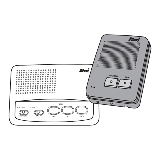
DOORBELL INTERCOM SECURITY SYSTEM WI-3P 3-CHANNEL INTERCOM ™ By Linear POWER IN USE LOCK CALL TALK DB-300 DOORBELL MODULE... -
Page 7: Wireless Intercom
Wireless Intercom 1. IN USE & POWER INDICATORS Lights when intercom is activated, lights when AC power is on. 2. POWER/VOLUME SWITCH Turns unit on and off, controls volume. 3. CHANNEL SELECTOR Allows you to select between channels. 4. LOCK BUTTON Press down for continuous monitoring. -
Page 8: Doorbell Module Installation
DOORBELL MODULE INSTALLATION Installing Using Existing Doorbell Wiring In a typical household doorbell system, the three components (doorbell button, TYPICAL HOUSEHOLD doorbell and doorbell transformer) are DOORBELL wired in a loop (see figure). DOORBELL TRANSFORMER WARNING! Before proceeding, turn off the circuit breaker (or remove fuse) that supplies current to your existing doorbell transformer. - Page 9 ALIGN TOP Attach doorbell module to doorbell EDGE FIRST mounting bracket (secure with retaining screw later after adjusting volume). SWING CLOSED SECURE WITH RETAINING SCREW Disconnect low-voltage (24 VAC) interior wires from existing doorbell transformer. REMOVE WIRES FROM SECONDARY SIDE OF DOORBELL TRANSFORMER TWIST WIRES TOGETHER Disconnect the two wires inside the...
-
Page 10: Installing As A New Independent System
12. A DB-301 system wired using the DB-300 existing doorbell wiring will be set up as shown in the figure. AC-12C 13. Plug adapter into an unswitched 110 VAC power outlet. Turn on circuit PLUG AC ADAPTER INTO UNSWITCHED breaker (or replace fuse) to restore 110 VAC OUTLET power to other devices on that circuit. - Page 11 SET CHANNEL Set doorbell module channel switches to SWITCH select intercom channel. For Channel “A” set Switch 1 ON and Switch 2 OFF. For Channel “B” set Switch 1 OFF and Switch 2 ON. CHANNEL "A" Switch 1 ON Switch 2 OFF CHANNEL "B"...
-
Page 12: Intercom Installation
INTERCOM INSTALLATION Choose where you want to plug in the PLUG INTERCOM wireless intercom that is being used as INTO 110 VAC OUTLET a doorbell. Make sure that the channel selector on each of the intercoms you install are on the same channel as the doorbell module. -
Page 13: Troubleshooting
TROUBLESHOOTING No Sound Check to see if channel selection is the same on doorbell module and wireless intercom. Make sure LOCK button on wireless intercom is up. Make sure wireless intercom is turned on and volume control is up. Make sure volume control on back of doorbell module is turned Make sure the light shines through on both buttons on front of doorbell module, if the lights are not there, this means electricity is not reaching the module. -
Page 14: Specifications
SPECIFICATIONS DESCRIPTION SPECIFICATION DOORBELL MODULE POWER SOURCE 12 VAC AT 60 Hz CARRIER FREQUENCY (A) 230 kHZ, (B) 260 kHz RF OUTPUT POWER 80 mW (70 mW - 100 mW) AUDIO OUTPUT POWER 500 mW STANDBY CURRENT 30 mA MAXIMUM CURRENT 180 mA DIMENSIONS 3"... - Page 16 Copyright © 1999 Linear Corporation 216082 B...
Need help?
Do you have a question about the DB-301 and is the answer not in the manual?
Questions and answers