Yamaha S80 Service Manual
Control synthesizer
Hide thumbs
Also See for S80:
- Owner's manual (164 pages) ,
- Data list (40 pages) ,
- Performance list (1 page)
Table of Contents
Advertisement
Quick Links
SY
011477
19991101-198000
CONTROL SYNTHESIZER
SERVICE MANUAL
CONTENTS
.................................................................... 7
CIRCUIT BOARDS
MIDI INPLEMENTATION CHART.......................................... 48
PARTS LIST
OVERALL CIRCUIT DIAGRAM
................................................... 3
.................................... 4
................. 5
............................ 6
.............................. 8
.............................. 13
................................. 18
...................................... 20
............................ 24/34
............... 44
HAMAMATSU, JAPAN
1.58K-9431
Printed in Japan '99.11
Advertisement
Table of Contents

Related Manuals for Yamaha S80


Summary of Contents for Yamaha S80
- Page 1 CONTROL SYNTHESIZER SERVICE MANUAL CONTENTS SPECIFICATIONS ........... 3 PANEL LAYOUT ........4 CIRCUIT BOARD LAYOUT ....5 BLOCK DIAGRAM ......6 WIRING ..............7 DISASSEMBLY PROCEDURE ......8 LSI PIN DESCRIPTION ......13 IC BLOCK DIAGRAM ......... 18 CIRCUIT BOARDS ........
- Page 2 IMPOR TANT NOTICE This manual has been provided for the use of authorized Yamaha Retailers and their service personnel. It has been assumed that basic service procedures inherent to the industry, and more specifically Yamaha Products, are already known and under- stood by the users, and have therefore not been restated.
- Page 3 SPECIFICATIONS KEYBOARD Number of Keys Touch Initial touch, After touch TONE GENERATION SYSTEM Tone Generators AWM2, Modular Synthesis Plug-in System Polyphony VOICE Number of Voice Normal voices (256 Presets, 128 Internals [Users], 128 Externals [Memory Cards]), Drum voices (8 presets, 2 Internals [Users], 2 Externals [Memory Cards]), Plug-in voices (64 x 2 Plug-in Boards [If installed]) Wave ROM 24 MByte PERFORMANCE...
-
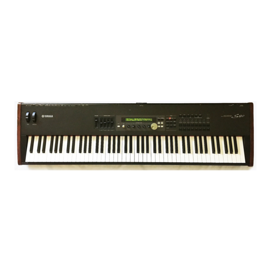
Page 4: Panel Layout
PANEL LAYOUT Front panel 11 10 L/MONO THRU FOOT FOOT FOOT AC INLET POWER GAIN ..A/D INPUT PHONES OUTPUT INDIVIDUAL OUTPUT VOLUME CONTROLLER SUSTAIN SWITCH BREATH TO HOST HOST SELECT MIDI 3.3V CARD ON / PRE1 PRE 2 PLG1 PLG2 MODE VOLUME... -
Page 5: Circuit Board Layout
Rear panel 5 6 7 8 9 3.3V CARD MIDI INDIVIDUAL OUTPUT OUTPUT POWER AC INLET FOOT FOOT FOOT THRU HOST SELECT TO HOST BREATH SWITCH SUSTAIN CONTROLLER VOLUME L MONO PHONES A D INPUT GAIN MIDI PC-2 PC-1 10 11 12 13 14 15 16 POWER switch... - Page 6 BLOCK DIAGRAM Control Panel SW 52 OPTION MIDI PANEL SCANING Slider MN101C027YB PLUG-IN CLK8MHz HOST TO HOST Smart Media BOARD SELECT Load/Save Slot x 2 Panel LED 15 DISPLAY LCD 40 2 LED BackLight IC50 IC12 PLUG-IN Smart MIDI toHOST IC22 Media CONTROL...
- Page 7 WIRING AE2 Keyboard Unit Keyboard After Touch PLUG-IN 1 PLUG-IN 2 Parts List Location Connector Assembly Remarks WHEEL Ref. No. After Touch DM-PS 11P/L1450 OVERALL 370 Sensor OVERALL 380 OVERALL 390 KRD-KRD 15P/L600 OVERALL 450 WHEEL 5P/L300 WHEEL 80 KRD-KRD 10P/L650 CONTROLPANEL 110 KRD-KRD...
-
Page 8: Disassembly Procedure
DISASSEMBLY PROCEDURE Remove the six (6) screws marked [300] from the Power Supply Unit bottom of the main unit and open the control panel Open the control panel assembly. (See procedure 1.) assembly by lifting it up. (Fig. 1) Remove the two (2) screws marked [30] and the five (5) screws marked [31]. - Page 9 〈 BOTTOM VIEW1 〉 [82] [92] Display assembly 〈 TOP VIEW 〉 [220] 〈 BOTTOM VIEW2 〉 [22] Display assembly PLG Angle POWER SUPPLY 〈 REAR VIEW 〉 [81] [130] [96] [31] [30] [31] [22]: Bind Head Tapping Screw-B 3.0X6 MFZN2BL (EP600230) [82]: Bind Head Tapping Screw-B 3.0X6 MFZN2BL (EP600230) [30]: Bind Head Tapping Screw-B 3.0X6 MFZN2BL (EP600230)
- Page 10 DM Circuit Board Open the control panel assembly. (See procedure 1.) Remove the JK circuit board. (See procedure 8.) Remove the seven (7) screws marked [282]. The DM shield cover can then be removed. (Fig. 4) Remove the three (3) screws marked [63]. (Fig. 4) Remove the two (2) screws marked [62] and the screw marked [64] from the DM circuit board.
- Page 11 PC Circuit Board 11-1 Open the control panel assembly. (See procedure 1.) 11-2 Remove the two (2) screws marked [250]. The PC circuit board can then be removed. (Fig. 6) Keyboard Assembly 12-1 Open the control panel assembly. (See procedure 1.) 12-2 Remove the four (4) screws marked [230] and the four (4) screws marked [240].
-
Page 12: Disassembly Procedure
Keyboard Disassembly Procedure 13-1 Remove the circuit board marked [A], and then remove the key spring marked [B]. (Fig. 7) 13-2 Press the part marked [D’] in the direction shown in figure 9, then remove the key marked [D] and the hammer assembly marked [C]. -
Page 13: Lsi Pin Description
LSI PIN DESCRIPTION HD64F7045F28 (XW419A00) CPU NAME FUNCTION NAME FUNCTION /WRHH HH write PE14 LCD data 6 input / output Data bus /WRHL PA21 MLAN insert detect PE15 LCD data 7 input / output VCC77 Power supply VSS6... - Page 14 HD63B01Y0RCE0F (XM234A00) CPU (PKS) NAME FUNCTION NAME FUNCTION /NMI Non-maskable interrupt M1/S8 Make contact of key receive/ M0/S7 Switch receive Ground Key scan drive ...
- Page 15 TC203C760HF-002 (XS725A00) SWP30B AWM Tone Generator coped with MEG) Standard Wave Processor NAME FUNCTION NAME FUNCTION (Ground) (Ground) HMD0 HMD1 HMD2 HMD3 HMD4 Address bus of internal register HMD5 HMD6 Wave memory data bus (Upper 16 bits) HMD7 HMD8 HMD9 CA10 HMD10 CA11...
- Page 16 MN101C027YB (XS711200) CPU NAME FUNCTION NAME FUNCTION Switch matrix data Switch matrix data MIDI transmit data VREF+ Power supply (+5V, analog) Switch matrix data Power supply (+5V) OSC2 Crystal oscillator (8MHz) OSC1 Crystal oscillator (8MHz) Ground Not used Not used MMOD Memory mode select (Grounded) Rotary encoder data...
- Page 17 PCM1800 (XU770A00) A/D Converter NAME FUNCTION NAME FUNCTION VINL Analog input (L ch.) LRCK Sampling clock input/output VREF1 Reference 1 decoupling cap. Bit clock input/output REFCOM Reference decoupling common DOUT Audio data output VREF2 Reference 2 decoupling cap. SYSCK System clock input VINR Analog input (R ch.) DGND...
-
Page 18: Ic Block Diagram
IC BLOCK DIAGRAM TC74VH04F (XM332A00) TC74VH32F(XN963A00) TC74VHC00F(XT229A00) Inverter IC29, IC55 IC73 MAND TC74LVC139FPEL(XS048A00) TC74VHC157FF(XN966A00) TC74VHC244F(XN969A00) IC26, IC42 IC103 IC51 Demultiplexer Multiplexer Bus Buffer VDD (Vcc) (GND) Vss TC74VHC245F(XT487A00) TC74VHC273F(XN971A00)IC52 TC7S66FF(XR682A00) IC11 SN74HC273NSR(XH223A00) IC30 Trabsceiver IC27, IC28 Analog Switch D-FF IN / OUT CLEAR OUT / IN COUT... - Page 19 M5M34051FP(XV103A00) DS90C402M (XW357A00) NJM4556AMT1(XQ138A00) NJM4556AD (XQ824A00) µPC4570G2 (XF291A00) IC12 IC23 IC102 Line Transceiver µPC4570C (XC520A00) Operation Amplifier Line Receiver IC62,IC65,IC73 Dual Operational Amplifier RI 2- RO 1 RI 2+ RI 1+ RO 2 +DC Voltage RI 1- Output A Supply +DC Voltage Output A +V 8...
-
Page 20: Output
TEST PROGRAM PC Circuit Board SV Circuit Board Test No. Test Item Test Conditions, Judgment Criteria, etc. RAM READ/WRITE OK/NG, (MAIN SRAM/WAVE DRAM) RAM BATTERY OK/NG, 2.7V or more, Less than 3.5V WAVE ROM OK/NG ON/OFF blinking alternately PANEL SWITCH/LED OK/NG ENCODER OK;... - Page 21 A. HOW TO ENTER THE TEST PROGRAM C. TEST SELECTION WHEN AN ERROR HAS BEEN DETECTED While pressing the [VOICE], [PERFORM] and [STORE] When the test result has been judged as “NG” in each of switches, turn on the [POWER ON/OFF] switch. The the following tests, choose whether to execute the same following message will then appear.
- Page 22 If the correct switch is pressed after that, testing will T3. WAVE ROM proceed to the next switch. If the test results for all switches are satisfactory, “OK” will appear. The switches are checked in the following order. This test compares each wave ROM data. [VOICE]>[PERFORM]>[STORE]>[UTILITY]>[CARD]>...
- Page 23 T7. KEYBOARD x x x: current knob value y y y: next target value This test is used to check that the keyboard functions properly by scaling 88 keys from A1 to C7. DISPLAY OF RESULTS (The above shows the C1 check.) (No change in the message on the display) x x x x: velocity value of the key being pressed TEST END...
- Page 24 Operate the FOOT VOLUME, FOOT CONTROLLER, T12. CONTROLLER SUSTAIN SWITCH and FOOT SWITCH according to the instruction on the LCD as described below. Check that the numbers change and that “OK” appears as the result. x x x: current knob value Release 0 (0-2);...
- Page 25 Connect a MIDI cable to MID IN and OUT, and then DISPLAY OF RESULTS begin testing. If the IN and OUT check results are “OK”, connect the MIDI monitor with THRU and check that the test pattern (AA•FF•00•55) is output. (No change in the message on the display) DISPLAY OF THE RESULTS TEST END...
- Page 26 T18. TO HOST DISPLAY OF RESULTS TEST END AUTO: when the [INC] switch is pressed, the Connect pin No.3 to pin No.5, and connect pin No.6 to sound output will stop and the next test No.8, and then execute testing. will be executed.
- Page 27 When a plug is not connected and the level is 2 or lower, With MIC 2, GAIN = MIC applies and the level of the “INSERT PLUG” appears and when a plug is inserted, signal input through the A/D will be lowered to the the A/D level will be indicated.
- Page 28 When the factory settings are not restored T25. mLAN TEST END Connect the mLAN board to the mLAN slot and execute The test ends after the result is displayed. testing. After checking the connection of the mLAN board, the signal FACTORY SETTING DATA transmission and reception of the MIDI line, the RESET request signal, and the operation of OUT + SWP30 of the...
- Page 29 Turn on the power while pressing [EXIT] and T28. EXIT [ENTER], and the system program will be loaded from SMART MEDIA and the operating power will be restored. When testing is executed, the following message will appear on the LCD. Turn on the power while pressing [DEC] and [INC], and the wave data will be loaded from SMART MEDIA, and the operating power will be...
- Page 40 When set to all, data will be output through the channel 1. 0011 0000 0111 0000 [SW6] PHRASE CLIP MODE JOB only. Not available on S80. 0011 0001 0111 0001 [SW7] In the VOICE MODE, VOICE related data only. In the PERFORMANCE MODE, PERFORMANCE...
- Page 41 When set to the number other than off, MIDI MASTER VOLUME will be received. *4 CS6x only. [SW6] PHRASE CLIP MODE JOB only. Not available on S80. *5 Transmitted/received only when MODE2 is selected in CONTROL CHANGE MODE. [SW7] In the VOICE MODE, VOICE related data only. In the PERFORMANCE MODE, PERFORMANCE *6 The default CONTROL NUMBERs of ASSIGNABLE CONTROLLER are as follows: related data only.
- Page 42 (3-6-1-2)IDENTITY REQUEST(Receive only) ank Select will be actually executed when the Program Change message is received. ank Select and Program Change numbers that are not supported by Yamaha will be gnored. F0H 7EH 0nH 06H 01H F7H ("n" = Device No.However, this instrument receives under "omni.")
- Page 43 HOST MODE = MIDI To Host From Host Local Sw MIDI Out MIDI In HOST MODE = PC1/PC2/MAC To Host From Host Local Sw MIDI Out MIDI In Although three types of note on/note off data, received via MIDI, played by the internal sequencer and played on the keyboard will be distinguished, the other controllers (channel messages) equally affect the entire notes.
Need help?
Do you have a question about the S80 and is the answer not in the manual?
Questions and answers