Table of Contents
Advertisement
Quick Links
Technical
Documentation
Hand-held Analyzer 2250 Light
With Sound Level Meter Software BZ-7130
1/1-oct. Frequency Analysis Software BZ-7131
1/3-oct. Frequency Analysis Software BZ-7132
Logging Software BZ-7133
Signal Recording Option BZ-7226 and
Tone Assessment Option BZ-7231
User Manual
English BE 1766 –21
Advertisement
Table of Contents
Troubleshooting

Related Manuals for B&K 2250 Light


Summary of Contents for B&K 2250 Light
- Page 1 Technical Documentation Hand-held Analyzer 2250 Light With Sound Level Meter Software BZ-7130 1/1-oct. Frequency Analysis Software BZ-7131 1/3-oct. Frequency Analysis Software BZ-7132 Logging Software BZ-7133 Signal Recording Option BZ-7226 and Tone Assessment Option BZ-7231 User Manual English BE 1766 –21...
- Page 3 2250 Light with the following 2250 Light Software: Sound Level Meter Software BZ-7130 1/1-oct. Frequency Analysis Software BZ-7131 1/3-oct. Frequency Analysis Software BZ-7132 Logging Software BZ-7133 Signal Recording Option BZ-7226 Tone Assessment Option BZ-7231 User Manual Valid for all hardware versions and from software versions 4.1 October 2012 BE 176621...
-
Page 4: Safety Considerations
Safety Considerations This apparatus has been designed and tested in accordance with IEC 61010 – 1 and EN 61010 – 1 Safety Requirements for Electrical Equipment for Measurement, Control and Laboratory Use. This manual contains information and warnings which must be followed to ensure safe operation and to retain the apparatus in safe condition. -
Page 5: Table Of Contents
CHAPTER 4 Getting to Know Your 2250 Light..............25 What is a Sound Level Meter?................25 What is 2250 Light? ................... 26 Sound Level Meter Software for 2250 Light BZ-7130........26 Built-in Help......................28 Software and Hardware Versions ..............28... - Page 6 Post-processing and Reporting................57 Internet Browser for Online Display and Control of the Analyzer....... 58 CHAPTER 8 Advanced Use of 2250 Light – Tips and Tricks ..........61 Setting your Preferences on 2250 Light............. 61 Display Settings ....................61 Power Settings....................62 Regional Settings....................
- Page 7 SD/CF Cards and USB Sticks................82 Battery Pack and Recalibration of Battery Charge Indicator......84 Touch Screen..................... 84 Reset Options ....................84 Services at Brüel & Kjær for Type 2250 Light............ 88 Accredited Calibration..................88 Initial Calibration ....................88 Regular Recalibration ..................88 Filter Calibration....................
- Page 8 10.3 Displaying the Results ..................92 Smileys ......................96 10.4 Saving Results ....................96 CHAPTER 11 Logging (Optional Module)................97 11.1 Setting up the Instrument................... 98 11.2 Controlling the Measurement................100 11.3 Displaying the Results ..................100 The Profile View....................101 Marking Sound Categories ................
- Page 9 Total Measurement ..................150 For BZ-7130, BZ-7131, BZ-7132 and BZ-7133 Software ........ 150 Logged Measurement ..................152 For Logging Software for 2250 Light BZ-7133..........152 Logged (100 ms) Measurement............... 154 For Logging Software for 2250 Light BZ-7133..........154 Instantaneous Measured Parameters (available at any time)......155 Processed Parameters for Display Only ............
-
Page 11: Chapter 1 Introduction
How to Use this Manual 1.2.1 Conventions Used in this Manual Instructions and descriptions that refer to 2250 Light pushbuttons are shown with the pushbutton icons as seen on the instrument. See Chapter 2 for a list of pushbutton icons and their functions. -
Page 12: Beginners
Web site, by typing ‘Primer’ in the search window. The Web site also con- tains lots of other information you might find useful. Further information is available in the On-line Help installed on 2250 Light. 1.2.3 Experienced Users of Acoustic Measurement Equipment The manual is designed so that you do not have to read all of it to be able to use the instrument. -
Page 13: Assembling Your 2250 Light
Chapter 2 Assembling Your 2250 Light This chapter describes how to assemble and set up a 2250 Light. It provides a brief description and an associated diagram showing the instrument’s components and the various input and output connections. This enables you to start getting familiar with the instrument, while assembling a system. -
Page 14: Instrument Components
2250 Light – User Manual Instrument Components An overview of the main instrument components is provided in Fig.2.1. The descriptions that follow refer to those components. Fig.2.1 Instrument components 1) Measurement Microphone: A Brüel & Kjær Prepolarized Free-field ½ Microphone is used. - Page 15 16) Top Socket: This is the microphone input socket for 2250 Light. The Measurement Microphone and Preamplifier (items 1 and 2 respectively) are connected directly to this socket. For more details see section 2.3 that follows 17) Tripod Mounting Thread: Use this to mount 2250 Light onto the tripod and/or tripod extension...
-
Page 16: Analyzer Inputs/Outputs
2250 Light – User Manual 18) Wrist Strap/Tripod Mounting Thread: Use this to attach the wrist strap to 2250 Light for added security, or use it to mount 2250 Light onto the tripod and/or tripod extension using the tripod adaptor UA-1673... - Page 17 7) Secure Digital Card Slot: Insert a SD or SDHC memory card to save data Hardware Version 4: Fig.2.3 Connector panel of 2250 Light for hardware version 4 1) Micro USB Interface Socket: Use the supplied Micro USB Cable AO-1494 to connect 2) Earphone Socket: Use the optional Earphones HT-0015 to connect...
-
Page 18: Description Of Inputs And Outputs
Top Socket See item 16 in Fig.2.1. This 10-pin LEMO connector is the microphone input for 2250 Light. Microphone Type 4950 (including Preamplifier ZC-0032) is normally connected directly to this connector. If required, however, one of two microphone extension cables (AO-0697-D-030, 3 m and AO-0697-D-100, 10 m), can be fitted between the preamplifier and the top socket, to extend the distance to the desired length. - Page 19 See item 5 in Fig.2.2 and Fig.2.3. Located above the USB connector, it is used to reset 2250 Light if you have problems with the instrument and cannot get it to operate. To reset, press the button with the point of the stylus.
- Page 20 2250 Light – User Manual Trigger Input Socket See item 8 in Fig.2.3. This triaxial LEMO connector is used for the external trigger of signal recordings. If you want to start and stop the recording using an external device, connect it to this input. See details in Appendix A.
-
Page 21: Hardware Setup
CHAPTER 2 Assembling Your 2250 Light Hardware Setup Fig.2.4 2250 Light – hardware overview UA-0237 90 mm Windscreen 4231 4950 Microphone Sound Calibrator ZC-0032 Microphone Preamplifier AO-0697-D-030 AO-0697-D-100 Microphone Microphone Ext. Cable, 3 m Ext. Cable, 10 m UA-1317 Microphone... -
Page 22: Assembling 2250 Light
Battery Pack QB-0061 comes charged to approximately half capacity on initial delivery. Before using your 2250 Light for the first time, it is recommended that you fully charge the battery pack, by connecting Mains Power Supply ZG-0426 (or ZG-0429) to the external power socket. -
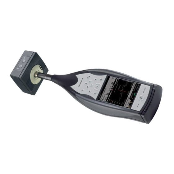
Page 23: Alternative Measurement Method (Extended Microphone)
Ensure that one of the three legs is pointing in roughly the same direction as your 2250 Light needs to point. (We will refer to this leg as the front leg.) 4) Position the extension stem at an angle of 45 to the horizontal and vertically in-line with °... -
Page 24: Measuring For Convenience
2250 Light – User Manual Connecting a Microphone Extension Cable There are two optionally available extension cables which are recommended for use with 2250 Light. These are: • AO-0697-D-030: 3 m long • AO-0697-D-100: 10 m long Note: Connecting a recommended microphone extension cable has no appreciable effect on the Hand-held Analyzer’s measurement and has no effect on the instrument’s calibration. -
Page 25: Making Your First Measurement
Making Your First Measurement This chapter describes how to make a basic measurement and how to save and document the results. It assumes you have just received your 2250 Light and are turning it on for the first time. Note: A stylus is stored in a holder on the side of the instrument, see item 15 in Fig.2.1. This can be used on the touch-sensitive screen to select icons and functions during the procedures that follow. -
Page 26: Congratulations
3.1.1 Congratulations! You should now be familiar with the basic principles of the 2250 Light. If you need more help, the following section goes into the measurement process in more detail. If not, please refer to Chapter 4. -
Page 27: Set The Sound Level Meter Project Template
CHAPTER 3 Making Your First Measurement 3.2.3 Set the Sound Level Meter Project Template After initialisation, the screen shown in Fig.3.1 appears: Fig.3.1 Initial sound level meter screen 1) Check that the SOUND LEVEL METER Project Template is displayed at the top of the screen, see Fig.3.1. - Page 28 2250 Light – User Manual Fig.3.3 Setting the measurement mode 3) Press the Start/Pause pushbutton to start the measurement. Note: Start appears on the screen as feedback when you press the Start/Pause pushbutton. Notice the Running Icon on the screen and monitor the red, yellow, green ‘traffic light’...
- Page 29 CHAPTER 3 Making Your First Measurement Fig.3.4 Measurement feedback in the status field 5) Toggle between different display parameters, as required, by tapping on each parameter field (for example LAF90.0 in Fig.3.4) with the stylus and selecting other parameters from the drop-down lists that appear. Note: The tabs at the bottom of the screen allow you to choose different ways of displaying the measurement results: •...
- Page 30 2250 Light – User Manual Fig.3.5 Main Menu options Change the broadband weighting parameters by tapping on the ‘plus’ icon next to Frequency Weightings, then on the weighting parameter field on the right-hand side of the screen. A weighting drop-down menu will appear, see Fig.3.6. Change the parameters as required.
-
Page 31: Save Your Measurement
Making Your First Measurement Save your Measurement When you have completed your measurement, you need to save it. By default, 2250 Light creates a job folder called JOB 01. Job folders represent the upper level of the data (or file) management system, with individual measurements or sets of data, represented by projects appearing under the relevant job. -
Page 32: Documenting Your Measurement
2250 Light – User Manual Fig.3.8 Viewing your measurement in Explorer 2) This opens the Data Viewer, see example in Fig.3.9. The viewer displays the data in a pre-defined format, where you can select and view different parameters, as necessary. - Page 33 CHAPTER 3 Making Your First Measurement If a GPS receiver is connected (via USB) when you press the Save pushbutton , then the GPS note is automatically created with the position. Remove the GPS receiver after usage to save power. Tap the paperclip , icon to see the GPS annotation in the project and tap the text icon in the annotation to view the GPS coordinates.
-
Page 34: Switching Off
2250 Light – User Manual Switching Off Switch 2250 Light off by pressing . If held in for 1 second, the instrument goes into standby mode; if held in for more than 4 seconds, it switches the instrument off. The instrument will automatically switch off, when it has been in standby mode without external... -
Page 35: Getting To Know Your 2250 Light
Once the signal is processed through the weighting filters, the resulting sound pressure level is displayed in decibels (dB) referenced to 20 µPa on the instrument’s screen. In 2250 Light, the sound pressure level values are updated at least once per second. -
Page 36: What Is 2250 Light
2250 Light running Sound Level Meter Software for 2250 Light, BZ-7130. If an A-weighting filter is used, it is expressed as , which is defined as the measurement of the equivalent continuous sound level using the A-weighted filter network. - Page 37 Instantaneous GPS data (requires a GPS device connected) Note: See Appendix B for a comprehensive list of all parameters. Sound Level Meter Software for 2250 Light, BZ-7130, incorporates a simple user interface, which is easy to learn and uses intuitive data storage and recall. Comprehensive security features means no loss of data, even on accidental power-off.
-
Page 38: Built-In Help
Post-process data (optional) • Export to other post-processing and documentation tools like Evaluator™ Type 7820 or ® ® Microsoft Excel or Word Measurement Partner Suite BZ-5503 is supplied on the Environmental Software DVD (BZ-5298), which is included with your 2250 Light. -
Page 39: Basic Principles When Using 2250 Light
CHAPTER 4 Getting to Know Your 2250 Light Basic Principles when using 2250 Light 4.4.1 Navigation Principles – ‘Star’ Navigation Concept The main principle is that all the main menus are accessible via a single tap of the stylus. The Main Menu icon forms the centre of the ‘star’... - Page 40 2250 Light – User Manual This configuration gives you immediate access to screens you need most, that is, those you will need to perform, save and document your measurements. The Main Menu allows you to navigate to the following screens: •...
-
Page 41: The Display Screen
CHAPTER 4 Getting to Know Your 2250 Light Transducers The Transducers screen is accessed from the Main Menu, you can view details of the transducer connected to the instrument. Details can be changed, see section 4.4.6. When you have finished viewing or updating the details, tap to return to the measurement screen. - Page 42 2250 Light – User Manual Fig.4.2 Project Template Typical screen when making a measurement Status field View area View tabs Shortcut bar with icons The main areas, starting at the top of the screen, are: • Project Template • Status Field •...
- Page 43 CHAPTER 4 Getting to Know Your 2250 Light Second Line: • Measurement state represented as icons: Stopped , Running and the Paused icon • Elapsed time of the measurement • Feedback on the action of pressing the following pushbuttons: Reset...
-
Page 44: Use Of Pushbuttons For Controlling Measurements
2250 Light – User Manual 4.4.3 Use of Pushbuttons for Controlling Measurements The design of 2250 Light is such that the layout of the pushbuttons has been optimised for single-handed operation. Reset Pushbutton Use the Reset pushbutton to reset a measurement, i.e., to reset all detectors, averagers, maximum and minimum hold, etc. -
Page 45: On-Screen Feedback And Traffic Light
4.4.5 Use of Stylus and Navigation Pushbuttons The stylus and navigation pushbuttons are used for setting up 2250 Light, navigating through the screens and managing the results. A number of items that appear on the screen (parameter values or icons) can be selected, updated and activated. - Page 46 2250 Light – User Manual Fig.4.3 Changing parameter values Stylus Usage Tap on the value you want in the drop-down, or tap outside the list to cancel the selection. Pushbutton Usage Use the navigation pushbuttons (up arrow , or down arrow...
-
Page 47: Locking The Pushbuttons And Display
CHAPTER 4 Getting to Know Your 2250 Light Character Keyboard When activating a text value, a standard full character keyboard appears on the screen (Fig.4.5). Fig.4.5 Character keyboard The character keyboard has all the functionality of a normal keyboard, enter text as required by tapping the individual keys with the stylus. - Page 48 2250 Light – User Manual...
-
Page 49: Chapter 5 Calibration
If no sound level calibrator is available (or a known amplification is introduced, i.e., by analyzing a tape recorded signal) then you can type the sensitivity directly into the Sensitivity field. 2250 Light will be regarded as uncalibrated and the text ‘Uncal.’ will appear in the status field. -
Page 50: Standard Calibration
To perform the acoustic calibration use Sound Calibrator Type 4231. It provides a stable sound pressure at 1 kHz and has minimal susceptibility to environmental factors. The procedure itself is relatively simple, and on 2250 Light the procedure is referred to as the Standard Calibration procedure. -
Page 51: Calibration Settings
Note: Detecting level... appears on the screen as feedback. 7) While 2250 Light is searching for the calibration signal and the signal level is stabilising, the ‘traffic light’ indicates a short green flash every second. When the level is stable, the traffic light indicates a steady green and the signal is measured and used for calibration. -
Page 52: Calibration History
You select the calibration history by tapping on the Calibration History link on the Calibration Details screen, see Fig.5.2. 2250 Light saves the last 20 calibrations, plus the initial calibration, which can be viewed on the Calibration History screen, see Fig.5.3. When you have finished, tap... -
Page 53: Transducer Database
Transducer Database The specifications for Microphone Type 4950 (and Preamplifier ZC-0032), which come fitted in the top socket of 2250 Light, are described on the Transducer Screen. 1) Select the Transducer Screen by tapping the Main Menu icon and choosing Transducers from the list of options. -
Page 54: Calibration Reminder
Status field. If the microphone is unknown to 2250 Light, no corrections can be made and no icon appears in the Status field. The parameters mentioned above have to be set manually (that is, typed in). We recommend that you insert the value for Nominal Sensitivity directly from the calibration chart. -
Page 55: Charge Injection Calibration
CHAPTER 5 Calibration • Send your instrument for Accredited/Traceable Calibration and update the Last Calibration date • Check the ‘Do not ask/remind again’ checkbox in the reminder pop-up (see example in Fig.5.7) • Disable the automatic calibration reminder Fig.5.7 Reminder pop-up You can set the Calibration Interval parameter to either 12 months or 24 months depending on your local requirements. -
Page 56: Performing A Manual Cic With Your 2250 Light
Cable Generator 970294/1 5.6.2 Performing a Manual CIC with your 2250 Light CIC is only available with Logging Software BZ-7133. Tap the Main Menu icon and select Calibration from the list. Click the CIC tab to view the various CIC parameters that are available. These include the results of the latest manual CIC, together with the reference, see Fig.5.9. - Page 57 CHAPTER 5 Calibration Fig.5.9 CIC Calibration tab The result of the Charge Injection Calibration consists of four parameters: • CIC Ratio • CIC Ratio Date • Deviation from Reference • CIC Result The CIC Result can be either: ‘Passed’, ‘Background noise too high’ or ‘CIC Ratio deviates from Ref.’...
- Page 58 2250 Light – User Manual...
-
Page 59: Chapter 6 Data Management
Project Name Prefix. Tap on the current name to reveal a keyboard for you to type in the required name. Projects are saved in folders which are called ‘jobs’ on your 2250 Light. These are similar to ® folders in the Windows... -
Page 60: Navigating In Jobs
2250 Light – User Manual Jobs can be created in the internal memory, on a Secure Digital (SD) Card, on a USB memory stick (hardware version 4 only), or for hardware versions 1 – 3, on a Compact Flash (CF) Card. -
Page 61: Selecting Default Measurement Job/Path
CHAPTER 6 Data Management To go down one level (that is, exit the Memory level), you tap on the job name (Internal Disk in this case) and select Open from the drop-down list – or you simply tap on the memory icon next to Internal Disk. -
Page 62: Viewing Data
2250 Light – User Manual 6.3.1 Viewing Data Use Explorer to locate the project with the results you want to view, then tap on the project name and select View from the drop-down that appears (or simply tap on the project icon). This will open the Viewer (Fig.6.2). -
Page 63: Re-Using Setups From Projects
CHAPTER 6 Data Management Fig.6.3 The Viewer for Logging data All the measured values are displayed below – Sound Level Meter data on the Data tab and spectrum information (Frequency Analysis only) on the Spectrum tab. Tap on the spectrum parameters or broadband parameters to select other parameters. - Page 64 2250 Light – User Manual Fig.6.4 Example of annotations attached to a project The Loudspeaker icon represents a signal recording. With hardware version 4, you can tap the annotation name and select Play from the drop-down that appears (or tap the icon) to play the recording using the headphone output.
-
Page 65: Connection To Pc Or Smart Phone
Chapter 7 Connection to PC or Smart Phone Introduction You can connect to your analyzer from a PC or smart phone in a number of different ways using a wide range of different connection types: • Use Measurement Partner Suite BZ-5503 for full control of the analyzer see section 7.2 –... -
Page 66: Transferring Measurement Data To Your Pc
2250 Light – User Manual Table 7.1 Connection overview Connection Available Connect from Settings in Preferences Type Notifications BZ-5503 Modem = Disabled – see section 8.2. BZ-5503, Internet Network Modem = GPRS/EDGE/HSPA Email Browser or Mobile GPRS/EDGE/H Dialup see section 8.4... -
Page 67: Connect To Your Pc
CHAPTER 7 Connection to PC or Smart Phone Using this software, measurements on the analyzer can be controlled from your PC and displayed online, using the same user interface on the PC as on the analyzer. Data transferred to the PC are organised in Archives. You can view the measurement data in the Archives. -
Page 68: Internet Browser For Online Display And Control Of The Analyzer
2250 Light – User Manual Analyzer Settings You access preferences by tapping on the Main Menu icon and selecting Preferences from the list of options (the screen shown in Fig.8.1 will appear). Tap on Remote Access Settings, or select the plus icon next to Remote Access Settings and set the Web Server Parameters to Enabled. - Page 69 CHAPTER 7 Connection to PC or Smart Phone Fig.7.2 Prompt for username and password The View Instrument Web Page Fig.7.3 shows the View Instrument web page, where you have an on-line display of the instrument. You can use the on-line display for monitoring the measurement only, you cannot change the display, or setup parameters, or start and stop measurements, etc.
- Page 70 2250 Light – User Manual The keyboard on the screen has the same functions as the instrument’s keyboard. Click on the display with the cursor to control the instrument as you do when tapping on the screen of the instrument.
-
Page 71: Advanced Use Of 2250 Light - Tips And Tricks
Chapter 8 Advanced Use of 2250 Light – Tips and Tricks Setting your Preferences on 2250 Light You can specify a number of parameters controlling display settings, power settings, regional settings and storage settings. These parameters are grouped together under Preferences. -
Page 72: Power Settings
8.1.2 Power Settings 2250 Light has an advanced power management function, that takes care of supplying the different circuits with adequate power and switches off those circuits that are not in use. These power management functions can be changed via the Power Settings screen, see Fig.8.3. - Page 73 CHAPTER 8 Advanced Use of 2250 Light – Tips and Tricks Fig.8.3 Power Settings screen Left: Hardware versions 1 – 3 Right: Hardware version The backlight will be switched on as soon as you operate the instrument, either by using the keyboard or the stylus on the touch-sensitive screen.
-
Page 74: Regional Settings
2250 Light – User Manual The instrument will automatically switch off when it has been in standby mode without external power for more than 30 hours. Note 1: If the instrument is powered externally the Standby After parameters are ignored and the instrument will never go to standby. -
Page 75: Storage Settings
8.1.4 Storage Settings Each time you save the results of a measurement, 2250 Light suggests a project name and number for the project. The Project Name Prefix can be generated automatically (from the start date of the project as Year, Month, Date in the format YYMMDD, for example, 051112 as 2005, November 12th) or you can specify a Project Name Prefix (max. -
Page 76: Printer Settings
2250 Light – User Manual You can listen to the measured signal for monitoring purposes. Select between A/B-weighted, C- weighted or Z-weighted. (A/B-weighting is determined by setting the parameter in Setup, Frequency Weightings, Broadband (excl. Peak)). The measured signal covers approximately 120 dB (from approximately 20 dB to 140 dB with a Type 4950 microphone of nominal sensitivity). -
Page 77: Modem/Dyndns Settings
CHAPTER 8 Advanced Use of 2250 Light – Tips and Tricks Modem/DynDNS Settings You can use the analyzer for monitoring in remote places and control it using Measurement Partner Suite BZ-5503, via a telephone connection – wired or wireless – using suitable modems or via network connections. - Page 78 2250 Light – User Manual When the Modem parameter is set to GPRS/EDGE/HSPA Dialup, then a connection is made using the settings in Dialup Networking. The Status parameter reflects the current status of the network connection – e.g., ‘Connected’ or ‘Disconnected’. If the connection fails, then the analyzer will try to reconnect –...
-
Page 79: Dyndns
CHAPTER 8 Advanced Use of 2250 Light – Tips and Tricks Compact Flash Modems The following modem has been tested: • Compact GPRS from Pretec (www.pretec.com) Compact flash modems can be inserted directly in the compact flash socket of the analyzer. -
Page 80: Network Settings
2250 Light – User Manual Note: To avoid too much traffic at DynDNS.com, the analyzer ensures that this service doesn't allow updates of settings more frequently than every 10 minutes. So you may experience up to a 10 minute wait for DynDNS settings to update. -
Page 81: Parameters In Network Settings
CHAPTER 8 Advanced Use of 2250 Light – Tips and Tricks Hardware version 4 accepts the following SD WLAN card: • P322 802.11abg SD WLAN from Socket Mobile (www.socketmobile.com) – Brüel & Kjær order number UL-1025 Hardware versions 1 – 3 accept the following CF LAN and WLAN cards: •... - Page 82 2250 Light – User Manual Selectable if Set IP Address = Manually Preferred DNS The IP address of the primary DNS server Alternate DNS The IP address of the secondary DNS server MAC Address The MAC Address of the network adaptor (LAN or WLAN) in use. MAC (Media Access Control) Address is a unique identifier assigned to the network adaptor.
-
Page 83: Notifications
CHAPTER 8 Advanced Use of 2250 Light – Tips and Tricks Notifications The analyzer can send you a daily status or notify you if disk space is getting low or external power has disappeared, etc. This is done via SMS or e-mail, as described in this section. The SMS/e-mail notification contains a short status report for the analyzer. -
Page 84: Text/Sms Notifications
2250 Light – User Manual Table 8.2 Content of Notification Information Type Content Reason for notification ‘Test’, ‘Alarm’ or ‘Status’ followed by a short description Time of notification Date and Time Instrument ID Serial No. and Location Status of current Disk... -
Page 85: E-Mail Notifications
CHAPTER 8 Advanced Use of 2250 Light – Tips and Tricks 8.4.3 E-mail Notifications E-mail notifications can be used if the analyzer is connected to a network with access to a mail server. This can typically be done if the analyzer is connected through LAN or by a GPRS/EDGE/HSPA serial modem (see section 8.2.2 and section 8.3). -
Page 86: Connecting To Weather Stations And Gps Receivers
2250 Light – User Manual Password Protection Connection to the instrument is password protected. There are two levels of protection: • Guest – for viewing only • Administrator – for viewing and controlling the instrument Username and Password Under Preferences you set the Username and Password individually for the Guest and for Administrator accounts. -
Page 87: Gps Receivers
CHAPTER 8 Advanced Use of 2250 Light – Tips and Tricks 8.6.2 GPS Receivers The analyzer can be connected to the following GPS receivers: • GPS Receiver ZZ-0249 – for measurement of latitude, longitude, altitude and position error Please refer to the user manual for Noise Monitoring Terminal Type 3639-A, B and C (BE 1818) for details on how to mount and connect the GPS receiver using Utility Unit ZH-0689. - Page 88 2250 Light – User Manual The Timer Setup lists the timers that have been defined previously on the analyzer (i.e., added by you or previous users). Fig.8.8 Example Timer Setup In the topmost line you can add other timers by tapping on the Add New Timer icon .
-
Page 89: Updating, Maintenance And Troubleshooting
If you purchase a separate software application for your 2250 Light, then you have to install the license on the instrument. This is done using Measurement Partner Suite BZ-5503, please consult the on-line help included with the BZ-5503 software for instructions on how to install a license. -
Page 90: Update Through The Internet
2250 Light – User Manual hardware version 1 – 3, install your preferred language (with G4 hardware, all languages are pre-installed in the analyzer). Installation requires a USB connection between BZ-5503 and the analyzer. The BZ-5503 software will clearly indicate if the new software version is an update (free of charge) or an upgrade (license fee). - Page 91 CHAPTER 9 Updating, Maintenance and Troubleshooting instrument will start. This will take 10-15 minutes and the analyzer will reboot when finished. Any unsaved logging data will be saved and the analyzer is ready to use again. 5) Connect to the instrument again and verify the new software version by tapping on the Help icon on the instrument's screen, then select About.
-
Page 92: Downgrade To An Earlier Version
Check that the microphone, including preamplifier, is correctly mounted in the top socket (or correctly connected to the extension cable) • Check that the transducer you have mounted on your 2250 Light is selected as the Transducer Used parameter, this is also found in the Setup menu •... - Page 93 The cards delivered by Brüel & Kjær have all been tested for their read/write performance in a 2250 Light and can be used for the applications available in a 2250 Light. If you need more (or other) types of memory devices, please consult your local Brüel & Kjær representative.
-
Page 94: Battery Pack And Recalibration Of Battery Charge Indicator
The adjustment procedure ends with saving the values or canceling the adjustment 9.3.5 Reset Options Reset Button WARNING:Unsaved data or setups will be lost when you reset the instrument. If your 2250 Light stops responding to pushbutton presses, or stylus taps, then you can do the following:... - Page 95 For hardware versions 1 – 3, you will reset the analyzer to a default state, where the user is set to 2250 Light and the project template is set to Sound Level Meter. The existing Sound Level Meter project template will be overwritten, as will the preferences for the user.
- Page 96 2250 Light – User Manual Fig.9.4 Update 2250 Light software screen c) Cancel the update by pressing any other pushbutton than the Accept pushbutton Fig.9.5 Reset to default settings screen d) Press the Accept pushbutton to reset to default settings.
- Page 97 Compact Flash card with installation files for 2250 Light. Power off 2250 Light and insert the compact flash card in the CF slot on the instrument. Then press and hold down the Manual Event 2...
-
Page 98: Services At Brüel & Kjær For Type 2250 Light
5 minutes. WARNING:Do not remove the CF-card while updating the 2250 Light software! When the 2250 Light software has been updated, you will get the option of resetting to the default settings. If the problem still persists, then you should contact your local Brüel & Kjær representative. -
Page 99: Hardware Maintenance And Repair
Brüel & Kjær representative. Care, Cleaning and Storage 2250 Light is a robust instrument, however, when handling, storing or cleaning your instrument, please take the following precautions. 9.5.1 Handling the Instrument •... -
Page 100: Storing The Instrument
2250 Light – User Manual 9.5.3 Storing the Instrument • Keep the sound level meter in a dry place, preferably within its carrying pouch • For long-term storage, remove the battery pack • Do not exceed storage temperature limits of –25 to +70°C (–13 to +158°F) -
Page 101: 1/1- And 1/3-Octave Frequency Analysis (Optional Modules)
(Optional Modules) 2250 Light has two optional Frequency Analysis modules, these are: • 1/1-octave Frequency Analysis Software for 2250 Light BZ-7131, enables you to make 1/1- octave measurements and broadband sound level measurements simultaneously • 1/3-octave Frequency Analysis Software for 2250 Light BZ-7132, enables you to make 1/3-... -
Page 102: Controlling The Measurement
2250 Light – User Manual FREQUENCY ANALYZER 1/1-OCTAVE (or 1/3-OCTAVE), tap on the black bar at the top of the screen and select FREQUENCY ANALYZER 1/1-OCTAVE (or 1/3- OCTAVE) from the drop-down that appears. 2) Tap the Main Menu icon and select Setup from the list of options. - Page 103 (including decimal point). The Spectrum view (which only appears as a tab if 1/1-octave or 1/3-octave Frequency Analysis Software for 2250 Light BZ-7131/32, is enabled), shows two different spectra being measured simultaneously. In the example in Fig.10.2, L and L...
- Page 104 2250 Light – User Manual Fig.10.3 Adjusting the X-axis 3) Scale the Y-axis (left-hand vertical scale of the graphical display) by tapping on the scale and accessing the drop-down menu, see Fig.10.4. (You can also select the spectrum cursor and press the Accept pushbutton.)
- Page 105 CHAPTER 10 1/1- and 1/3-octave Frequency Analysis (Optional Modules) Spectrum Table shows the displayed part of the spectrum in tabular form – as in Fig.10.5. Press the Table Format icon at the top of the screen to select between two different viewing formats: –...
-
Page 106: Smileys
2250 Light – User Manual Fig.10.6 Displaying a Noise Curve together with the L spectrum For RC and NCB you also have the possibility of displaying the limit curves for Rumble and Hiss, and for Rattle and Vibration together with the 1/1-octave L spectrum. -
Page 107: Logging (Optional Module)
Chapter 11 Logging (Optional Module) Logging Software for 2250 Light BZ-7133 enables you to measure and save data periodically on SD or CF cards. You can also save to a USB memory stick with hardware version 4. The module is optimised for attended use, which means that while measuring you can ‘mark’ up to five different sound categories on-line. -
Page 108: Setting Up The Instrument
Sound Level Meter and Frequency Analyzer measurement, see Chapter 3 and Chapter 10 respectively. These settings are common to both the logging and the total measurement. Requires 1/1- or 1/3-octave Frequency Analysis Software for 2250 Light BZ-7131/32... - Page 109 Marker 2: ‘Event 1’ – controlled by pressing the Manual Event 1 pushbutton • Marker 3: ‘Event 2’ – controlled by pressing the second Manual Event 2 pushbutton • Marker 4: ‘Marker 4’ • Marker 5: ‘Marker 5’ Requires 1/1- or 1/3-octave Frequency Analysis Software for 2250 Light BZ-7131/32...
-
Page 110: Controlling The Measurement
2250 Light – User Manual All markers can be controlled by the stylus in the Profile display. You can set a Pre-marker Time between 0 and 5 seconds. This will start markers 1, 2 or 3 the set number of pre-marker seconds before the point where the Back-erase pushbutton or the Manual Event pushbuttons are pressed. -
Page 111: The Profile View
CHAPTER 11 Logging (Optional Module) 11.3.1 The Profile View The Profile view displays a profile of a logged broadband parameter (dB versus time). This is very convenient when marking sound categories on-line or annotating the measurement. See Fig.11.2. Fig.11.2 Profile View (showing extended status field) Status Field The Status Field has been extended to include an extra line of information below the two... - Page 112 2250 Light – User Manual • Step forwards or backwards through the logging intervals on all displays, using the icons. (The icons are also connected to the profile cursor, so that any corresponding movement backwards or forwards through the intervals in one display will be reproduced...
-
Page 113: Marking Sound Categories
An Event Marker – this allows you to mark a particular sound of interest during your measurement On 2250 Light, Marker 1 is used as an Exclude Marker, while Markers 2 to 5 are used as Event Markers. All four event markers can be user-defined. You can define a marker by tapping on the Main Menu icon and selecting Setup, followed by Markers. -
Page 114: Editing Markers On Profiles
2250 Light – User Manual Marking During the Measurement The measurement parameter is displayed as a progressing profile. Use of pushbuttons: Press the Back-erase pushbutton to start an Exclude Marker (marker number 1). The marker is displayed above the profile. Press the button once more to stop the Exclude Marker. -
Page 115: Saving And Recalling Results
CHAPTER 11 Logging (Optional Module) 4) Select Delete for the marker you want to narrow from the drop-down menu. The part where the marker overlaps the gap between the two cursors will be deleted. To delete a marker: 1) Tap and hold the stylus in the profile display at a position to the left of the marker you want to delete. - Page 116 2250 Light – User Manual...
-
Page 117: Signal Recording (Optional Module)
Chapter 12 Signal Recording (Optional Module) Signal Recording Option BZ-7226 allows you to record the input signal (typically sound) in either 16-bit or 24-bit resolution during measurement. The signal recording can be controlled manually or by using an external trigger signal. The recorded sound can be played back and listened to using the optional Earphones HT-0015. - Page 118 2250 Light – User Manual 2) Depending on your memory device: • Insert an SD memory card in a SD card slot at the bottom of the analyzer • If you have hardware versions 1 – 3, you can insert a CF memory card in the CF card slot at the bottom of the analyzer •...
-
Page 119: Controlling The Recording
CHAPTER 12 Signal Recording (Optional Module) 9) Under Input you specify Trigger Input if you want to start the signal recording using an external trigger signal. See details in Appendix A. To exit the screen, tap the icon. 12.1.2 Controlling the Recording The measurement is controlled in the same way you would control a normal Sound Level Meter measurement, using Start/Pause, Continue, Reset and Save pushbuttons, see Chapter 3 for more details. -
Page 120: With Logging Software
2250 Light – User Manual 12.2 With Logging Software You can use the Signal Recording facility together with the Logging Software. You can record the sound for the whole measurement period or you can record sound for controlled parts of the measurement. -
Page 121: Controlling The Recording
CHAPTER 12 Signal Recording (Optional Module) recording Time and Post-recording Time to specify how much extra you want to be recorded before and after the event • Off, if you do not want to record the signal 6) Set Recording Quality to High, Medium, Fair or Low in accordance with your needs, note, however, that the high quality requires more disk space than low quality –... -
Page 122: Control Recording Using The Stylus
2250 Light – User Manual When Recording Control is set to External Event, and Trigger Input is set to Voltage Level, then recording is started when the voltage level is ‘high’ and stopped when voltage level is ‘low’ (details in Appendix A). Duration Limit has no effect on this setting. -
Page 123: Playing The Recording
12.2.4 Playing the Recording With your G4 2250 Light, you can playback the sound simply by selecting part of the marker – as described in section 11.3.3 – and choose Play Sound from the resulting drop-down menu. The following drop-down menu will then appear, see Fig.12.2. -
Page 124: Signal Recordings On The Pc
2250 Light – User Manual Fig.12.3 Playing the recording – output level pop-up When you have selected the method of play-back, a pop-up appears explaining how to adjust the output level in the headphone and how to stop the play-back. - Page 125 CHAPTER 12 Signal Recording (Optional Module) Signal Recordings can be input to the Brüel & Kjær PULSE Multi-Analyzer platform for further analysis – please contact your local Brüel & Kjær representative for further information. Note: When recording signals for further analysis in PULSE, be sure to record the Z-weighted signal and select Automatic Gain Control to Off under the Signal Recording parameters and select the Recording Quality to match your needs for frequency content –...
- Page 126 2250 Light – User Manual...
-
Page 127: Tone Assessment Option Bz-7231 - 1/3-Octave Method
If you have purchased 2250 Light together with the software application(s), then the relevant license(s) comes pre-installed on the analyzer. If you purchased a separate software application for your 2250 Light, then you have to install the license on the analyzer. This is done using BZ-5503, please consult the on-line help included with the BZ-5503 software for instructions on how to install a license. -
Page 128: Iso 1996-2, Annex D - Tone Assessment Calculations
2250 Light – User Manual adjustment shall be added to the A-weighted time averaged level, L . The first evaluation of audible tones in noise is most often carried out by the human ear. But for comparative analysis results, and documentation, an objective analysis may be needed. -
Page 129: Setting Up The Analyzer
CHAPTER 13 Tone Assessment Option BZ-7231 – 1/3-octave Method • Middle frequency range: includes the 1/3-octave bands from 160 Hz to 400 Hz with a level difference for a detected tone greater than 8 dB • High frequency range: includes the 1/3-octave bands from 500 Hz to 10 kHz with a level difference for a detected tone greater than 5 dB With BZ-7231 software, frequency ranges and the limit for the level differences in low, middle and high range can be set by the user. -
Page 130: Setting Up A Measurement Manually
2250 Light – User Manual 13.3.2 Setting up a Measurement Manually ISO 1996–2, Annex D You can set the division between the Low and Middle frequency range, the division between the Middle and High frequency range, and also the limits for the level differences between adjacent bands –... -
Page 131: Signal Recording
CHAPTER 13 Tone Assessment Option BZ-7231 – 1/3-octave Method Fig.13.4 Pop-up window for tone measurement setup check The pop-up window can be de-activated for the rest of the measurement session. To activate it again, you will have to reload the template or restart your analyzer. This automatic check is deactivated when the Tone Assessment parameter is set to Off in the Setup menu. -
Page 132: Measuring
2250 Light – User Manual Note: When signal recordings are to be used for re-analysis on a PC, be sure to set Automatic Gain Control parameter to Off, under the Signal Recording parameters, and set the Recording Quality parameter to High and Resolution to 24 bit. - Page 133 CHAPTER 13 Tone Assessment Option BZ-7231 – 1/3-octave Method Fig.13.6 The differences to the left and right of the selected frequency band are shown in the tone parameter panel – in this example, there is a 11.4 dB difference to the left and a 3.9 dB difference to the right The information shown in the value panel can be changed by tapping in the field.
-
Page 134: Logging Software Bz-7133 Template
2250 Light – User Manual 13.5 Logging Software BZ-7133 Template The results from the tone assessment can be found in the Spectrum view of the Logging template. Tone assessment is performed for each logging period, as well as for the total measurement time, see Fig.13.8. -
Page 135: Recalling Saved Measurements
CHAPTER 13 Tone Assessment Option BZ-7231 – 1/3-octave Method If you have selected 1/1-octave or a Direct input, tone assessment will be performed, but a smiley will be displayed. When you tap the smiley it will advise you to use a Microphone. For an overview of all the remedies associated to the various smileys, please refer to Table 13.2 Table 13.2 Overview of smileys and associated remedies... - Page 136 2250 Light – User Manual...
-
Page 137: Chapter 14 Specifications
Chapter 14 Specifications This chapter comprises the specifications that are needed for evaluation of instrument performance characteristics and proper use of the instrument. Some of the applicable sound level meter standards require additional technical documentation, in particular for pattern evaluation (type approval) purposes, but have no bearing on normal use. The additional technical documentation is given in a separate Brüel &... - Page 138 2250 Light – User Manual Hand-held Analyzer Type 2250-L (2250 Light) Platform Specifications apply to 2250 Light fitted with USER INTERFACE Microphone Type 4950 and Microphone Preamplifier Measurement Control: Using pushbuttons on ZC-0032: keyboard Setup and Display of Results: Using stylus on touch...
- Page 139 CHAPTER 14 Specifications Power Environmental EXTERNAL DC POWER SUPPLY REQUIREMENTS WARM-UP TIME Used to charge the battery pack in the instrument From Power Off: <2 minutes Voltage: 8–24 V DC, ripple voltage <20 mV From Standby: <10 seconds Current Requirement: min. 1.5 A TEMPERATURE Power Consumption: <2.5 W, without battery IEC 60068–2–1 &...
- Page 140 • Administrator level: for viewing and full control of the • Guest level: for viewing only instrument Software Specifications – Sound Level Meter Software for 2250 Light BZ-7130 Conforms with the following National and International For Display and Storage: Standards:...
- Page 141 CHAPTER 14 Specifications MEASURING RANGES • Yellow LED flash every 5 s = stopped, ready to When using Microphone Type 4950 measure Dynamic Range: From typical noise floor to max. level • Green LED flashing slowly = awaiting calibration for a 1 kHz pure tone signal, A-weighted: 16.4 to signal 140 dB •...
- Page 142 Software Specifications – 1/1-octave Frequency Analysis Software for 2250 Light BZ-7131 and 1/3-octave Frequency Analysis Software for 2250 Light BZ-7132 The specifications for BZ-7131 and BZ-7132 include...
- Page 143 CHAPTER 14 Specifications Spectrum Data Stored at each Logging Interval: Markers are set using the stylus on the touch screen, All, or up to three selectable spectra (license for or the three marker pushbuttons BZ-7131 or BZ-7132 required) Calibration Logging Time: From 1 s to 31 days with 1 s resolution Measurement Total: For the logging time, in parallel CIC (CHARGE INJECTION CALIBRATION) with logging: All broadband data, statistics and spectra...
- Page 144 Measurements on 2250 Light can be controlled from Acoustic Determinator Type 7816, Evaluator Type the PC and displayed on-line with the PC, using the 7820, Protector Type 7825 or Qualifier (Light) Type same user interface on the PC as on 2250 Light 7830 (7831) DATA MANAGEMENT POST-PROCESSING...
- Page 145 2250 LIGHT SOFTWARE UPGRADES AND LICENSES HELP The utility software controls 2250 Light software Concise context-sensitive help in English upgrades and licensing of the 2250 Light applications PC REQUIREMENT ® INTERFACE TO 2250 LIGHT Operating System: Windows 7 or XP (both in 32-bit...
- Page 146 Lightweight Tripod 2250-L-EW 1 Extended Warranty, one year UA-1654 5 Extra Styli extension INTERFACING 2250-L-MU 1 Upgrade of 2250 Light to Type BZ-5503-A Logging Module (see Product 2250, performed at headquarters Data BP 2430) 2250-L-UPG Upgrade of software applications BZ-5503-B...
-
Page 147: A.1 Input
Appendix A Setup Parameters This appendix describes all the setup parameters included in a template. Input Table A.1 Input parameter Parameter Values Comment Sound Field Correction Free-field Select a correction matching the sound field of Diffuse-field your measurements. that is, you can make correct measurements in a diffuse-field using a Type 4950 free-field microphone, by selecting Diffuse-field correction. -
Page 148: Frequency Weightings
2250 Light – User Manual To compensate for this, use the built in windscreen correction. Table A.2 Windscreen correction parameter Parameter Values Comment Windscreen Correction None You can manually select a windscreen correction UA-0237 for Windscreen UA-0237. No correction is made... -
Page 149: Bandwidth
APPENDIX A Setup Parameters Table A.3 (Cont.) Frequency weighting parameters Parameter Values Comment Spectrum The frequency analysis (1/1-octave or 1/3-octave) will be frequency weighted in accordance with this parameter Note: X = frequency weighting A or B. ‘A’ requires that the Broadband (excl. Peak) parameter is set to AC or AZ. -
Page 150: Measurement Control
2250 Light – User Manual Table A.5 (Cont.) Statistics parameters Parameter Values Comment Percentile N2 0.1 to 99.9 User-defined percentile level where the value of is exceeded for N2% of the elapsed time Percentile N3 0.1 to 99.9 User-defined percentile level where the value of... -
Page 151: Logged Broadband
APPENDIX A Setup Parameters Table A.6 (Cont.) Measurement control parameters Parameter Values Comment Synchronize with Clock Select Yes to synchronize the logging intervals with whole minutes or hours, for example, if Logging Period is set to 00:01:00 (1 minute) and you start the measurement at 8:12:33, then the first logging interval will be from 8:12:33 to 8:12:59 (27 seconds), the second will be from 8:13:00 to 8:13:59 (60... - Page 152 2250 Light – User Manual Table A.7 (Cont.) Logged broadband parameters Parameter Values Comment Parameter 1 to This parameter can be set if Broadband Parameter 10 Parameters = Selected X = frequency weightings A or B Aeq,T,mov (controlled by Setup – Frequency Weightings –...
-
Page 153: Logged Broadband (100 Ms)
APPENDIX A Setup Parameters Logged Broadband (100 ms) Table A.8 Logged broadband (100 ms) parameters Parameter Values Comment Select On to log L (with an elapsed time of 100 ms and a logging period of 100 ms) Note: Logging L every 100 ms requires Broadband (excl. -
Page 154: Markers
2250 Light – User Manual Markers Table A.10 Markers Parameter Values Comment Marker 1 Text string Default set to ‘Exclude’. This marker can be set using the stylus in the profile or the Back- erase pushbutton during a measurement Marker 2 Text string Default set to ‘Event 1’. -
Page 155: A.10 Signal Recording
APPENDIX A Setup Parameters A.10 Signal Recording Table A.11 Signal Recording parameters Parameter Values Comment Recording Control Determines how recording of the measured signal is controlled Automatic Set to Automatic to start the recording when the measurement Manual Event is started and record throughout the measurement, only limited by the Maximum Duration Exclude Event Set to Manual Event to start recording manually while... - Page 156 2250 Light – User Manual Table A.11 (Cont.) Signal Recording parameters Parameter Values Comment Automatic Gain To ease identification of sound sources by listening, the gain Control can be automatically adjusted to keep the average level within a 40 dB range. When playing back the recorded signal, you will then hear clearly the whole signal content, whether the level has been 20 dB or 140 dB.
-
Page 157: A.11 Occupational Health
APPENDIX A Setup Parameters Table A.11 (Cont.) Signal Recording parameters Parameter Values Comment Post-recording 0 to 300 s Use this parameter to specify how much extra you want to be Time recorded after the trigger conditions are no longer fulfilled Duration Limit Use this parameter to enable the Minimum Duration and Maximum Duration parameters for overruling the duration of... - Page 158 2250 Light – User Manual Table A.12 (Cont.) Occupational health parameters Parameter Values Comment Threshold Level 0 to 140 dB Any sound levels below the threshold value do not contribute to the Dose measurement data. The time resolution for this calculation is 1 s for calculation of Dose and ProjDose –...
-
Page 159: Measurement Parameters
Appendix B Measurement Parameters This appendix describes the measurement parameters. They are measured in accordance with the setup parameters. Please refer to the Glossary in Appendix E for a description of the parameters. The following letters are substituted in the parameters that follow to represent the wide range of frequency weightings, time weightings and percentile levels available: V = frequency weightings A, B, C or Z (controlled by SETUP\FREQUENCY WEIGHTINGS\ BROADBAND PEAK parameter) -
Page 160: Total Measurement
2250 Light – User Manual Total Measurement B.1.1 For BZ-7130, BZ-7131, BZ-7132 and BZ-7133 Software The following parameters are measured within the Elapsed Time: Equivalent Continuous Sound Levels • • • • (not saved with data) Aeq,T,mov • Aeq,T,mov,max Sound Exposure Level •... - Page 161 APPENDIX B Measurement Parameters US Occupational Health Parameters • avRQ • • • DoseRQ • ProjDoseRQ General Parameters • Overload in % • Start time • Stop Time • Elapsed Time (excl. pauses) Special Parameters • (also called L XIeq •...
-
Page 162: Logged Measurement
Position error (dependant on type of GPS unit) Logged Measurement B.2.1 For Logging Software for 2250 Light BZ-7133 Parameters measured within a logging interval – up to ten (or all) of the following parameters can be logged: Equivalent Continuous Sound Levels •... - Page 163 APPENDIX B Measurement Parameters Maximum Time-weighted Sound Levels • XFmax • XSmax • XImax • YFmax • YSmax • YImax Minimum Time-weighted Sound Levels • XFmin • XSmin • XImin • YFmin • YSmin • YImin US Occupational Health Parameters •...
-
Page 164: Logged (100 Ms) Measurement
WFmin • WSmin Logged (100 ms) Measurement B.3.1 For Logging Software for 2250 Light BZ-7133 The following Broadband parameters can be logged every 100 ms • • • These parameters require a license for either BZ-7131 or BZ-7132, and measurement of spectra. -
Page 165: Instantaneous Measured Parameters (Available At Any Time)
APPENDIX B Measurement Parameters Instantaneous Measured Parameters (available at any time) Instantaneous Time-weighted Sound Levels • • • • • • Sound Pressure Levels (maximum time-weighted sound levels once per second) • XF(SPL) • XS(SPL) • XI(SPL) • YF(SPL) • YS(SPL) •... -
Page 166: Relationship Between Setup And Measurement Parameters
2250 Light – User Manual The following ISO/EU Occupational Health Parameters are calculated and displayed for Total, Periodic Reports and Logged data: • ep,d • ep,d,v If Statistics are available, then Std.Dev. and 7 percentile levels can be calculated and dis- played: LXN1 or LXUN1 to LXN7 or LXUN7. - Page 167 APPENDIX B Measurement Parameters Table B.3 Occupational Health Parameters Parameter L Dose ProjDose #VPeaks LavRQ TWA TWA Dose- Proj- ep,d ep,d,v (>NNNdB) DoseRQ Sound Field Correction Wind- ...
- Page 168 2250 Light – User Manual...
-
Page 169: Instrument Parameters
Appendix C Instrument Parameters This appendix describes the parameters for microphones and calibration. Current Transducer Table C.1 Current transducer parameter Parameter Values Comment Transducer Used (that is, Name and serial number of This parameter selects which connected to Top Socket) transducer transducer is connected to the Top Socket (displayed in Setup... -
Page 170: Calibration History
2250 Light – User Manual Table C.2 (Cont.) Microphone setup parameters Parameter Values Comment Microphone Type 4950 If microphone is a known type, then the rest of 4952 0° the parameters of the transducer are set 4952 90° automatically. Sound Field Correction and 4184-A 0°... - Page 171 Initial 2. Calibration date & Time YYYY-MM-DD hh:mm:ss 2. Sensitivity Double 2. Preamplifier ID No. Text string 2. User 2250 Light 2. Input Top Socket 2. Calibration Type External, Internal, Check 2. Calibrator Serial No. Text string 2. Comment Text string 2.
-
Page 172: Calibration Setup
6.6 Hz – 15.0 kHz 5.6 Hz – 16.5 kHz Diffuse-field a. From the typical total inherent noise level for the microphone and Type 2250 Light, to the overload limit for a sinusoidal signal at 1 kHz. b. Only with hardware version 4... -
Page 173: Preferences
Appendix D Preferences This appendix describes the parameters that are common to all project templates and can be set as preferences. Display Settings Table D.1 Traffic light, backlight and decimal place parameters Parameter Values Comment Traffic Light Brightness Normal High Key Backlight Backlight Brightness Minimum... -
Page 174: Power Settings
2250 Light – User Manual Power Settings Table D.2 Power settings parameters Parameter Values Comment Backlight Dim After 30 sec. Select optimum value for full After 1 min. backlight on (brightness After 2 min. determined by Backlight After 5 min. -
Page 175: Regional Settings
APPENDIX D Preferences Regional Settings Table D.3 Regional settings parameters Parameter Values Comment Decimal Point Select your preferred decimal point Date Separator Select your preferred date separator Date Format yyyy-MM-dd HH:mm:ss Select your preferred date dd-MM-yyyy HH:mm:ss format: HH = 24 hour, hh = 12 MM-dd-yyyy HH:mm:ss hour, XX = AM or PM yy-MM-dd hh:mm:ss XX... -
Page 176: Storage Settings
2250 Light – User Manual Storage Settings Table D.4 Storage settings parameters Parameter Values Comment Auto-naming of Projects Select Yes for automatically naming projects from the project start date as Year, Month, Date in the format YYMMDD, (for example, 051112 as 2005,... - Page 177 APPENDIX D Preferences Table D.5 (Cont.) Headphone settings parameters Parameter Values Comment Automatic Gain Control To ease identification of sound sources, the gain can be automatically adjusted to keep the average level within a 40 dB range. You will hear clearly the whole signal content, whether the level has been 20 dB or 140 dB...
-
Page 178: Printer Settings
2250 Light – User Manual Printer Settings Table D.6 Printer settings parameters Parameter Values Comment Printer Used None Select None if you don’t have a printer connected to 2250 Light Select MPS for a Mobile Pro Spectrum thermal printer from... -
Page 179: Modem/Dyndns Settings
APPENDIX D Preferences Modem/DynDNS Settings Table D.7 Modem/DynDNS settings parameters Parameter Values Comment Modem Disabled Set to Disabled if you do not have a modem GPRS/EDGE/HSPA Dialup connected; if you have connected a modem, but only want to use the SMS facility of the modem;... -
Page 180: Network Settings
2250 Light – User Manual Network Settings Table D.8 Network settings parameters Parameter Values Comment Location Up to 20 characters Use Location to specify a text identifying the analyzer or location of the analyzer. The Location will be displayed on the PC... - Page 181 APPENDIX D Preferences Table D.8 (Cont.) Network settings parameters Parameter Values Comment Name Up to 32 characters Name (SSID) of network you want to connect to. Update the name either by entering a name directly, or by tapping on the Available Networks and selecting a name from the list Security Open...
-
Page 182: Notification Settings
2250 Light – User Manual Notification Settings Table D.9 Notification settings parameters Parameter Values Comment Notification Disabled, Set to Disabled to disable notifications. E-mail, Set to E-mail to send notifications as e-mail when an alarm occurs. Set to SMS to send notifications as SMS when an alarm occurs. - Page 183 APPENDIX D Preferences Table D.9 (Cont.) Notification settings parameters Parameter Values Comment Account <string of characters> The account is typically the e-mail address of the e-mail used for sending the e-mail. *) Examples: myaddress@gmail.com myaddress@hotmail.com User Name <string of characters> The User Name is typically the e-mail address of the e-mail used for sending the e-mail.
-
Page 184: D.10 Remote Access Settings
2250 Light – User Manual D.10 Remote Access Settings Table D.10 Remote access settings parameters Parameter Values Comment Web Server Disabled Set Web Server to Enabled to enable display and Enabled control of the analyzer on a web page - see section 7.4. -
Page 185: Appendix E Glossary
Appendix E Glossary A-weighting Filter: Frequency weighting corresponding approximately to the 40 dB equal loudness curve, that is to say, the human ear’s response at low to medium sound levels. It is by far the most commonly applied frequency weighting and is used for all levels of sound. - Page 186 2250 Light – User Manual Our hearing covers a surprisingly wide range of sound pressures – a ratio of over a million to one. The dB scale makes the numbers manageable Dose, ProjDose: The Noise Dose is the equivalent averaged A-weighted Noise Level (taking...
- Page 187 APPENDIX E Glossary DoseUQ, ProjDoseUQ: The Noise Dose is the averaged A-weighted Noise Level (taking the Threshold Level into account) with Time Weighting U = F or S and Exchange Rate Q = 4, 5 or 6 for an 8 hour period (reference duration) relative to the maximum allowed (the Criterion Level) –...
- Page 188 2250 Light – User Manual Frequency Weighting A ‘C-weighting’ curve is also used, particularly when evaluating very loud or (contd.): low-frequency sounds. L p (dB) –20 –40 –60 Frequency (Hz) 100 200 500 10k 20k 000055 Sound Exposure Level – sometimes abbreviated SEL and sometimes called Single Event Level, is the Sound Exposure expressed as a level.
- Page 189 APPENDIX E Glossary The noise level exceeded for 90% of the measurement period with A-frequency AF90.0 weighting and Fast time weighting. The level is based on statistical analysis of a parameter (LAF or LAS) sampled at 10 ms intervals into 0.2 dB wide classes. The percentage is user-definable.
- Page 190 2250 Light – User Manual Loudness, Loudness Loudness is the subjective judgement of intensity of a sound by humans. Level: Loudness depends upon the sound pressure and frequency of the stimulus and whether the sound field is diffuse- or free-field. The unit is the Sone.
- Page 191 APPENDIX E Glossary Occupational Health Typical Setup Parameter settings for Occupational Health measurements in Standards: accordance with various standards: • OSHA (Occupational Safety and Health Administration) – 29 CFR 1910.95 • MSHA (Mine Safety and Health Administration) – 30 CFR 62.0 UMHRPEL •...
- Page 192 2250 Light – User Manual SIL, PSIL, SIL3: SIL (Speech Interference Level) is the arithmetic average of the 500 Hz, 1 kHz, 2 kHz and 4 kHz octave band levels. PSIL (Preferred Speech Interference Level) is the arithmetic average of the 500 Hz, 1 kHz and 2 kHz octave band levels.
-
Page 193: Index
Update or Upgrade..........79 Alarm Settings Parameters........172 Applying Tone Assessment........125 All Events..............110 Archive Data............. 28 Alternative Measurement Method......13 Assembling your 2250 Light ........3 Analyzer Asterisk About ..............28 Next to Project Name .......... 21 Advanced use ............61 Next to Template .......... - Page 194 2250 Light – User Manual Backlight Interval ..............45 Brightness ............63 Last Date..............45 Icon ..............33 Manual ..............39 Settings ............... 62 Nominal Sensitivity..........44 Backlight Brightness Parameter ......163 of Filters ...............88 Backlight Dim Parameter........164 Procedures............40 Bandwidth Parameters ........... 139 Reminder .............44...
- Page 195 INDEX via LAN ..............70 Display Settings............61 via LAN Modem ........... 67 Parameters............163 via Network ............55 Document Measurement .......... 22 Dose ............... 176 Weather Stations ..........76 Wired ..............70 DoseUQ..............177 Wireless ............... 70 Downgrade Software..........82 Connection Overview..........
- Page 196 2250 Light – User Manual Frequency Analysis Paused Measurement..........33 1/1- or 1/3-octave ..........91 PC ................32 Settings ............... 91 Power Supply............33 Frequency Analysis Software Recording............109 Calculated Parameters........95 Running Measurement.........33 Controlling Measurement ........92 Stopped Measurement.........33 Displaying Results..........92 Windscreen ............33 Save Results ............
- Page 197 INDEX Pushbuttons ............37 Log In as Another User ..........87 Jobs ................21 Logged (100 ms) Measurement Parameters..154 Copy/Paste ............51 Logged Broadband (100 ms) Parameters ..143, 154 Deleting ............... 51 Logged Broadband Parameters ......141 Description............49 Logged Measurement Parameters ......
- Page 198 2250 Light – User Manual Managing Data ............49 Micro USB Cable AO-1494 .........7 Manual Calibration ........... 39 Microphone ..............4 Manual Event ...........99, 108 Connecting............13 Disconnecting ............13 Marker ............... 104 Manual Event 2 Pushbutton ........5 Extension .............13 Manual Event Pushbutton .......... 5 Extension Cable..........
- Page 199 INDEX Noise Curve .............. 95 Transducer ............159 Noise Parameters ............. 95 within Elapsed Time .......... 150 Nominal Sensitivity ........... 44 Passwords..............58 Parameters............174 Notification Settings Parameters ......172 NR..............95, 180 Paused Icon ............. 33 NR Decisive Band........... 180 PC Connection ............
- Page 200 2250 Light – User Manual Project Name Prefix ..........65 Recording Quality Parameter........145 Project Name Prefix Parameter......166 Recording Signals..........54, 107 Project Template Bar..........32 Reference Time ............181 Reference Time Parameter........147 Projects ..............21 Asterisks.............. 21 Regional Settings............64 Changing the Template ........17 Parameters ............165...
- Page 201 INDEX Selecting Input ..............10 Parameter Values ..........35 Long ..............112 Template.............. 17 Manual Triggers ..........108 Parameters............145 Weighting Parameters ......... 20 Server Settings Play Back ............102 NMT ..............174 Play Back on PC ..........114 Web ..............174 Playing...............
- Page 202 2250 Light – User Manual Sound Field Corrections........... 44 Microphone ............33 Sound Level ............182 Overload ..............33 Sound Level Meter Paused..............33 Power..............8 Description ............25 Sound Level Meter Software ........15 Running..............33 Instantaneous Measured Parameters ....27 Stopped..............33 Set Up ..............17 Uncal..............33...
- Page 203 INDEX Timers............... 77 Mounting.............. 13 Add and Delete ............ 78 Mounting Thread ........... 5 Setup ..............78 Tripod Extension Stem UA-1651......13 Tripod UA-0587 ............13 Tips and Tricks ............61 Tone Assessment Troubleshooting............82 According to ISO 1996-2, Annex D....117 Battery ..............
- Page 204 2250 Light – User Manual Views................ 32 Wind Broadband............19 Parameters ............76 Central Area ............33 Speed..............65 Wind Speed Unit Parameter ........165 Profile ..............101 Spectrum ............. 93 Windscreen ...............13 XL ................ 19 Corrections............44 Icons ..............33 Windscreen Correction Parameter......138 Warm Start ............... 16 Wireless LAN ............70...
- Page 208 HEADQUARTERS: Brüel & Kjær Sound & Vibration Measurement A/S · DK-2850 Nærum · Denmark Telephone: +45 7741 2000 · Fax: +45 4580 1405 · www.bksv.com · info@bksv.com Local representatives and service organisations worldwide...
Need help?
Do you have a question about the 2250 Light and is the answer not in the manual?
Questions and answers