
Subscribe to Our Youtube Channel
Related Manuals for B&K 1076


Summary of Contents for B&K 1076
- Page 1 TELEVISION Model 107 6 ANALYST & K MANUFACTURING- COMPANY 1801 W. BELLE PLAINE AVENUE, CHICAGO 13, ILLINOIS...
- Page 3 · INSTRUCTION MANUAL Model 1076 TELEVISION ANALYST B & K MANUFACTURING COMPANY 1801 West Belle Plaine Avenue Chicago 13, lliinois...
-
Page 4: Table Of Contents
TABLE OF CONTENTS Page What It Will Do........... . . 3 Controls-What They Do.......... - Page 5 MODEL 1076 TELEVISION ANALYST What The Model 1076 Television Analyst Will Do: Some idea of the versatility of the Model 1076 Television Analyst can be gained from a quick check of the following list of major equipment features and uses.
-
Page 6: Controls-What They Do
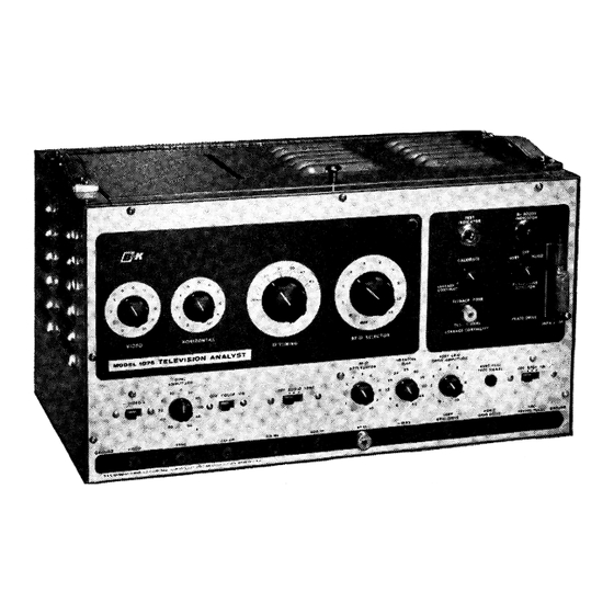
Main Controls The following main operating controls are provided on the front panel of the Model 1076 Television Analyst. (See Figure 1). 1. POWER SWITCH. This Switch is labeled Off-Stby-On, and permits the unit to be kept at readiness by using the Stand-by position to keep the tubes hot, yet prevents any radiation of signal from the unit. - Page 8 6DQ6 6AX4 a[!] 4.SM;C, 6CA4 6AN8 O SC . 10TH B&K MFG. V-1 1 TUBE &CONT ROL CHICAGO. ILL. LAYOUT. 1076 6DQ6 12AX 7 ½A SLO-BLO LINE USE3A 931A • IN, �= s0 R - 211\2) osc. 6CG7 L-201 f§\...
-
Page 9: How To Set Up The Analyst
7. HORIZONTAL DRIVE. (C-219). This capacitor controls the hori zontal drive to the horizontal output tube. Adjustment of this con trol establishes the operating conditions for the horizontal output tube and is effective in adjusting the horizontal linearity. 8. L-201 (Horizontal Oscillator Stabilizing coil). This coil assists in stabilizing the Horizontal oscillator frequency and is slug tuned. - Page 10 2. Tune in the station test pattern on the receiver. Find the mechanical center of receiver screen and adjust set so center of station pattern coincides with this point. Adjust receiver for good linearity, size and centering. Switch on and off the station several times to be sure the horizontal circuit of the receiver is not set at a critical point.
-
Page 11: Operation Of The Analyst
OPERATION OF THE TELEVISION ANALYST In order to become familiar with the operation of the Television Analyst it is suggested that you set up, on a bench, an operating TV receiver. In this way you will become familiar with the procedure and with the available signals and their uses. - Page 12 operation may be necessary to accomplish this. (For example Channel 3 & 4). Allow the monitor receiver to sync to the On-the Air signal and observe the Analyst signal :floating by horizontally. Adjust the HORIZONTAL control so that the Test Pattern picture stands straight up and barely floats by the TV station picture.
- Page 13 me I.F. frequencies. You will notice that when you tune to the correct I.F. frequency you will again see the test pattern and hear the tone on the monitor receiver. Tune for best picture and sound. 14. Move the R.F.-1.F. output cable from the first I.F. to the grid and plate of the second I.F.
- Page 14 picture is not in sync, rotate sync amplitude control to the opposite phase, or -50 volts. This illustrates how the sync signal is used. 19. Plug the test lead into the 400 cycle Audio Tone jack and connect the other end of the cable to the grid of the first audio amplifier tube.
- Page 15 the Television Analyst. The scan will not necessarily be linear but provides an excellent test on the vertical output transformer and yoke. Disconnect the Plate Drive test lead and reinsert the vertical output tube in the test receiver. Turn the Plate nrive Selector switch to the "OFF"...
-
Page 16: Trouble Shooting With The Television Analyst
TROUBLE SHOOTING WITH THE TELEVISION ANALYST The Television Analyst provides the service technician with a powerful tool to quickly and accurately trouble shoot television receivers. Outputs are provided, to enable the service technician to inject signals into any section of a TV receiver to isolate trouble to (1), a section of a receiver, and (2), to the specific stage. -
Page 17: Trouble Shooting, Intermittents
HOW TO USE THE TELEVISION ANALYST FOR TROUBLE SHOOTING INTERMITTENTS TV receivers which come into the shop for intermittent troubles can be extremely time consuming and cause a great deal of irritation to the service man. This is especially true when the technician cannot even isolate the sec tion of the receiver where the source of the trouble is located. - Page 18 are lost when the intermittent trouble appears, it is obvious that the trouble must be in the R.F. tuner, I.F. amplifier, Video detector, Video amplifier or A.G.C. circuits. The Television Analyst will now be used to locate the source of the trouble. The signals available from the instrument will be injected into the receiver at various points, so that by the process of elimination the trouble can be analyzed down to one stage.
- Page 19 capacitor (See Figure 5). The intermittent condition again appears, placing the blame for intermittent loss of signal to the coupling capacitor C-4 which is opening up intermittently. ( If it were the first video amplifier tube itself, screen bypass capacitor C-1, plate load resistor R-2, peaking coil L-4, or any other component in the first video amplifier circuit, the trouble would not have appeared with the signal injected at point (H) in the circuit.
-
Page 20: Trouble Shooting, Loss Of Audio
We will now shift our sync signal to the plate of the 6AU6 sync separator and again observe the picture on the face of the CRT. We now find that the intermittent sync condition occurs. This tells us that the trouble lies between the plate circuit of the 6AU6 sync separator and the grid circuit of the 6BF6 sync amplifier. -
Page 21: Trouble Shooting, Sync Amplifiers And Sync Separator Stages
5000 135V. AUDIO OUTPUT A. r. AMP. .00 47 Mr D IMEG VOLUME 3 3 K CONTROL 6.8K 1500..R. . 0 0 260V . 260V. Figure 7-A typical TV audio system HOW TO TROUBLE SHOOT SYNC AMPLIFIERS AND SYNC SEPARATOR STAGES With the Television Analyst it is possible to quickly and thoroughly check the sync separator stages of any television receiver. - Page 22 antenna terminals. It would be desirable not to inject the test pattern signal into the video amplifier stages because we might do this beyond the point where the sync signal take-off occurs. Rather than spend time looking for this point, inject the signal as indicated above. The next step is to apply a composite sync signal from the Television Analyst to the grid (and chassis or B-) of V2, Fig.
- Page 23 As a precautionary rule, whenever you reach a point in the sync separator system where the injected pulses do not lock in the picture, try both polarity pulses. If you find that one polarity of sync pulse does lock in the picture, the stage is operating satisfactorily.
-
Page 24: Trouble Shooting, A.g.c. Systems
Consider now what happens when noise pulses appear at the same time. These noise pulses will be transferred first to grid No. 1 and if they are strong ° enough, they will cut this grid off. The same noise pulses, reversed 180 will appear at grid No. - Page 25 and the test pattern signal tuned in. The displayed picture appears in Fig. 11. We must now take the video output signal from the Analyst and inject this signal to the grid of the 1st video amplifier. The result is viewed on the television receiver's picture tube.
- Page 26 Since the picture displayed in Fig. 11 could be caused by overload of the I.F. stage it might be wise at this point to determine the signal handling capabilities of these stages. By reducing the setting of the R.F.-I.F. Attenuator on the Television Analyst we are capable of lowering the level of the I.F.
-
Page 27: Trouble Shooting Vertical Sweep Circuits
and an external bias supply, control can be maintained. If both of the conditions are met then the trouble is definitely A.G.C. If only one test is passed then the trouble must be peculiar to the l.F. stage under test. TROUBLE SHOOTING VERTICAL SWEEP CIRCUITS The following steps should be taken when checking the vertical deflection systems. -
Page 28: Trouble Shooting Horizontal Deflection Circuits
tube. The vertical output tube itself is removed from the set. In sets where the heaters are series-wired, the filament terminals on the socket can be shorted out, so that all the other tubes in the series string will continue to operate. We are now driving the output transformer from the vertical out... - Page 29 plate of this stage. In essence, then, we can completely bypass the horizontal output tube. A second innovation is two indicator lights which further serve to pin-point troubles in the output transformer, or the high voltage network. The lights operate on a "go - no-go" basis, clearly revealing to the serviceman the presence or absence of certain hard-to-find troubles.
- Page 30 Drive jack to the plate lead connection on the horizontal output transformer. Be sure the hi voltage indicator lamp is connected to the plate cap lead going to the hi voltage rectifier and that this lead is removed from the plate cap of the tube. Apply power to the re ceiver and observe the B+ boost indicator lamp on the front of the TV Analyst and the hi voltage indicator.
- Page 31 output stage from the horizontal oscillator. This coupling capacitor is frequently the cause of much difficulty in the horizontal output circuit. If C-2 becomes leaky or shorted, a positive voltage will be applied to the control grid of the horizontal output stage ,from the plate circuit of the oscillator.
- Page 32 NOTE: For the boost indicator to light up, R.F. pulses must be present on the plate of the horizontal output tube. This, in tum, means that boost B+ must be present, for without this additional voltage, any R.F. pulses produced will be too weak to light up the boost indicator.
- Page 33 Make careful note where the yoke wires connect in the circuit. Also keep the yoke disconnected while the remaining tests are being made. Next the width coil is tested. To do this, it is disconnected com pletely 'from the circuit. Note the effect upon the boost indicator •...
- Page 34 until the test indicator lamp just goes out. Connect the flyback trans former to this cable. The connection is made from horizontal output plate cap connector to hi voltage rectifier plate cap connector. If the test indicator glows this indicates that the transformer has shorted turns.
-
Page 35: Trouble Shooting Chroma Circuits
could be developed by the circuit and it would prevent the develop ment of the normal amount of high voltage or the normal amount of horizontal drive for the yoke. If C-2 should open, the circuit would again be disrupted by the lack of boost B+ voltage. B+ voltage, however, would still appear because the damper tube and L-1 would still be intact. - Page 36 from yellow to orange, red, blue and ending in green. 'l'his method of pro ducing the color signals is called off-set sub-carrier operation. By referring to Fig. 18 you will see the vector display of the color infor mation that can be obtained for a phase shift of any given number of degrees. °...
-
Page 38: How To Adjust Color Purity And Convergence
The color demodulators are now properly aligned so that no + (R-Y) signal gets through the (B-Y) demodulator, and also no (B-Y), signal gets R-Y DEMOD. OUTPUT Figure 20-(R-Y) demodulat.or output as seen on an oscilloscope through the + (R-Y) demodulator. Also the front panel hue control is in the middle of its range to allow variations in both directions if necessary. - Page 39 Since static convergence is primarily concerned with the center dot, the serviceman must make his adjustments to this dot. Figure 22 in the instruction manual show the motion of the red, green and blue dots which the static con vergence magnets will produce. Careful adjustment of the static . convergence magnets will cause the three dots to superimpose and become white.
- Page 40 1. Adjust the red vertical parabola amplitude and phase control to make the red vertical bar, along the vertical axis of the raster, parallel or coincident with the associated blue bar. 2. Adjust the blue vertical parabola amplitude and phase controls to make the horizontal blue bars, along the vertical axis of the raster, equally spaced or coincident with their associated hori...
-
Page 41: Other Uses For The Analyst
OTHER USES FOR THE TELEVISION ANALYST Displ ing Your Own Pictures and Patterns on Any TV Receiver The Television Analyst will transmit any positive and transparent picture or pattern. The only requirement is tliat the size of the pattern be limited to 3-by-4-inches. - Page 42 Shading or gamma check. Determine frequency response at To set proper size set Shaded areas provide point where lines of wedge merge. top and bottom of circle good check for video ,__- to top and bottom edges Bandwidth shown in megacycles. amplifier linearity.
- Page 44 venience, a block diagram of the complete instruments is shown in Fig. 26. Many of the circuits in this instrument are quite familiar to the service technician, because they are used in most television receivers. Some of these circuits are new and greater emphasis will be placed upon the description of these circuits.
- Page 45 The electrical impulses which have been produced as a result of the light variation on the photomultiplier tube are developed across the photomultiplier load resistor R-102 on your schematic. This is a 1000 ohm resistor. The video signal is capacity coupled to the grid of V-2A. V-2A is the first video amplifier.
- Page 46 output jack by merely rotating the sync amplitude and phase control.. V-4B is the crystal controlled color subcarrier oscillator. This oscillator is factory adjusted to a very precise frequency to assure the proper rainbow display or · color bar display when used in trouble shooting color television receivers. The R.F.
- Page 47 capacity coupled to the grid of the horizontal output stage. A horizontal drive control is provided and is of the series type. Maximum capacity, representing maximum drive to the horizontal output system. The horizontal output trans former and high voltage circuits are conventional and are the auto transformer type using a 6AX4, V-12, as the damper tube, and a 1X2, V-13, as the high voltage rectifier.
-
Page 48: Service Adjustments
SERVICE ADJUSTMENTS The following section will deal with the method of adjusting the various auxiliary controls contained in the Television Analyst. Locations of these controls can be found by raising the cover. A tube and control layout diagram is located on the inside of this cover. THE SYNC LEVEL control R-121, is adjusted in the following manner. - Page 49 • to zero beat. In the absence of a standard oscillator, the following technique Lan be used. Using a standard TV receiver tuned to a broadcast station, adjust the discriminator circuit for an absolute zero output indicating that the discriminator is tuned correctly. Turn the Television Analyst on and obtain a picture and sound carrier on the TV receiver and adjust L-401 the 4.5 me oscillator adjustment in the Television Analyst for exactly zero output on the TV receiver discriminator.
-
Page 50: Service Information
SERVICE INFORMATION The enclosed schematic contains complete voltage chart and all key wave forms to assist in trouble shooting the Television Analyst. The instrument contains two fuses. Both are accessible from the top of the instrument and are located just in front of the 5BKPV1 scanning tube. The Line Fuse is a 3 ampere fuse while the B+ fuse is a ¼... - Page 51 WARRANTY Your B&K TELEVISION ANALYST is made of the finest material and then carefully tested at the factory before shipment. It carries the standard RETMA warranty against defects in material and workmanship for a period of 90 days from date of purchase. Should any defect be discovered within this warranty period, return the unit to the distributor from whom it was purchased.
- Page 52 WARRANTY "B & K warrants that each instrument manufactured by it will be free from defects in material and workmanship under normal usage and service for a period of ninety days after its purchase new from an authorized B & K distributor. Our obligation under this warranty is limited to repairing, or replacing any instrument or component which we are satisfied does not conform with the fore...
- Page 53 VOLTAGE CHART PIN NUMBERS 6 � 8 TUBE - - - - - ,- -150 270 -265 931A - - -- 12AT7 - .9 A.C. A.C. ---- -- 12AU7 A.C. -- -- f--- f--- 12AT7 V.A.C. V.A.C. -- -- � -- -- 6CB6 A.C.
- Page 54 MODEL 1076 VOLTAGE WAVEFORMS Fig. 2. COMPOSITE VIDEO at grid Fig. 3. COMPOSITE SYNC at grid of Fig. 1. VIDEO only from photomulti sync paraphase (V3A), 100V G-1 (V 4A} of modulator, 1 V plier obtained at G-1 of V2A P.P.
- Page 55 BOARD#4 LAST 'C- 419' 'C-404 NOT USED' R-33 LAST'R-414"� F A RAD PF=MICRO-MICR O ILLINOIS CHICAG O -:-- SHORTED CHASSIS-- LAST "C-18'' TURNS NALl1 ,,.,..un, a-o-,a 1076 SCHEMATI C LAST 'R- 3o" CALIBRATE ..... M-788-...
- Page 56 R ,t3 LA ST "R- 414" PF=MICRO-MICRO FARAD 8, 6. K. MF'G. CO., I NC. LEAKAGE -= SHORTED CHASSIS- LAST TURNS LAST 'R-415 1076 SCHEMATIC CALIBRATE ·c-ts. a-�- �o ..n, 15,S,C� 1�--<# i�ijUL D ... -!-UI ..�"" C.
- Page 57 B & K MODEL 1076 PARTS AND PRICE LIST l&K DEALER'S SCHEMATIC SYMIOL DESCRIPTION PART No. Gray Handle ......•...•... H-225 Lid Knob ........H-248 Centering Device ....•.....•... H-249 Rubber Feet ........H-250 Panel Mic. Jack ......... J-16 Audio Input Jack <Rear Apron> ....J-32 Black Output Jack ......
- Page 58 B & K MODEL 1076 PARTS AND PRICE LIST SCHEMATIC B&K DEALER'S SYMBOL DESCRIPTION PART No. CAPACITORS 20 MFD @ 350V Non-Polariz ed Electrolytic ..CL-20-350NP $1.26 20 MFD @ 50V Electrolytic Cap ..•..••... CL-20-50 500 MMF @ 20 KV Ceramic Capacitor ..... CC-501-20KV 1.50...
- Page 59 B & K MODEL 1076 PARTS AND PRICE LIST SCHEMATIC B&K DEALER'S SYMBOL DESCRIPTION PART No. L-301 I.F. Coil Less Slug & Form ......L-28 L-302 Channel No. 2 Coil Less Slug & Form ....L-29 L-303 Channel No.
- Page 60 B & K MODEL 1076 PARTS AND PRICE LIST DEALER'S SCHEMATIC B&K SYMBOL DESCRIPTION PART No. MISCELLANEOUS SR-1 } 65 MA Selenium Rectifier w/Mtg. Bracket ..E-65B S R-2 ½ Amp, "Slo-Blo" Fuse 3 AG <H.V.) ....F-2 1 3 Amp. Line Fuse ........ F-19 NE51 Bulb ........
- Page 61 TMOtl"I...
- Page 62 Tll10 ff '=I...
- Page 63 Tll'I Off ":I...
- Page 64 T�Off� ---------------- ---------------- ---------------- ---------------- ---------------- ---------------- ---------------- ---------------- ---------------- ---------------- ----- ----- ----- - ----------------...
Need help?
Do you have a question about the 1076 and is the answer not in the manual?
Questions and answers