Table of Contents
Advertisement
Advertisement
Table of Contents

Related Manuals for Matco Tools ADMM50


Summary of Contents for Matco Tools ADMM50
-
Page 2: Table Of Contents
Table of Contents Title Page No. INTRODUCTION ..............SAFETY PRECAUTIONS/WARNINGS ......SPECIFICATIONS ............... CONTROLS AND INDICATORS ........TESTING PROCEDURES ..........10 AUXILIARY FUNCTIONS ............ 17 BATTERY AND FUSE REPLACEMENT ......18 MAINTENANCE..............19 LIMITED ONE YEAR WARRANTY ........22 SERVICE PROCEDURES ..........22 REPLACEMENT PARTS ............. -
Page 3: Introduction
INTRODUCTION Congratulations. You have purchased a precision instrument manufactured to the highest quality standards. This Digital Automotive Tester is a general-purpose instrument designed for use in general electronics, home electrical applications, and automotive electrical/electronic systems. This tester is designed to test or measure AC voltage, DC voltage, DC current, AC current, resistance, diodes, continu- ity, frequency, duty cycle, pulse width, rpm and temperature. -
Page 4: Specifications
Always inspect the tester, test leads and any other acces- sories for damage prior to every use. If any damage is found, do not use tester until repairs are done. Always consider electrical and electronic equipment to be ener- gized (live). Never assume any equipment is de-energized. Do not connect probes to any available (unused) terminal while the meter is connected to a hazardous live circuit. - Page 5 Automatic zero adjustment Over range indicator (except 15 A function). Displays "OL" on LCD Low battery indicator. Displays battery symbol on LCD Automatic power shut off (after 10 idle minutes) Pollution Degree 2 Measuring circuit category II Operating environment: Temperature - 32° to 104° F. (0° C to 40° C) Humidity - Less than 80% relative humidity (non-condensing) Altitude - up to 6562 ft (2000 meters) Storage environment:...
- Page 6 ACV TRMS NOTE: Specifications are AC-coupled true RMS. Range Resolution Accuracy Overload Protection 400mV 100μV ±(1.2% of 250V DC RMS reading +8 digits) ±(0.8% of reading +8 10mV digits) 600V DC/AC RMS 400V ±(1.2% of reading +8 600V digits) Input Impedance: 10MΩ for all ranges. Frequency Response: 50 –...
- Page 7 DC CURRENT (AMPS) Range Resolution Accuracy Overload Protection 40mA 10μA ±(1.5% of 0.5A/250V fast fuse reading +5 Input Voltage 400mA 100μA digits) Drop: <0.2V. ±(2.5% of Unfused; 15sec maximum *15A 10mA reading +5 Input Voltage Drop: <0.2V. digits) * A waiting period of at least 15 minutes is necessary between every 15 second testing period.
- Page 8 TEMPERATURE Range Accuracy Overload Protection 32°F to 104°F ±5°F/±3°C (0°C to 40°C) -58°F to 392°F ±1.5%/±5°F (-50°C to 200°C) (±1.5%/±3°C) 0.5A/250V fast fuse 392°F to 752°F ±2%/±5°F (200°C to 400°C) ±2%/±3°C) WARNING To avoid fire and/or electrical shock hazards, DO NOT connect the thermocouples to circuits greater than 30 Vrms, 42.4 Vpk or 60 Vdc.
-
Page 9: Controls And Indicators
WARNING Risk of Explosion. This equipment has internal arcing and sparking parts, which should not be exposed to flammable vapors. This equipment is only suitable for installation in a garage having sufficient air circulation to be considered a non-hazardous location. WARNING Ignition coils produce a very high voltage. - Page 10 Temperature Function (Fahrenheit): Measures tempera- ture in °F. Auto-ranging from -58°F to +752°F. (Optional “K- Type” thermocouple required). Press SEL button (see item 19) to select desired function: ACmA Function: Measures AC current in milliamps. One range: 0 to 400 milliamps. DCmA Function: Measures DC current in milliamps.
-
Page 11: Testing Procedures
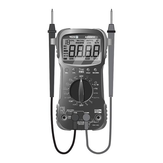
15A Input Jack. For red test lead probe connection when measuring high DC current (up to 15 amps only). DWELL ANGLE, MS °C, °F, BAT, ACmA/DCmA, CLAMP CURRENT, RPM and COP Input Jack. Liquid Crystal Display (LCD): Displays results of tests or measurements. - Page 12 Plug the BLACK test lead into "COM" jack of the tester; plug the RED test lead into the "V" jack. NOTE: If alligator clip adapters (not included with tester) are to be used on the test leads, use suitable rated and UL certified alligator clips.
- Page 13 NOTE: A diode is a semiconductor device that lets current flow in one direction only. If the diode to be tested is part of a circuit (with other electronic components), you must isolate it from the other components by disconnecting at least one side of it from the circuit before testing.
- Page 14 E. FREQUENCY MEASUREMENT Frequency is the number of times that an event repeats itself during a one-second time period. Frequency is measured in Hertz (Hz). Plug the RED test lead into the “Hz” jack of the tester; plug the BLACK test lead into the "COM" jack. Set the tester’s Function/Range Selector Switch to the Hz position (see Controls and Indicators, Item 4).
- Page 15 H. TEMPERATURE MEASUREMENT WARNING To avoid fire and/or electrical shock hazards, DO NOT connect the thermocouples to circuits greater than 30 Vrms, 42.4 Vpk or 60 Vdc. NOTE: Temperature measurement requires use of an optional “K-type” thermocouple. Plug the Positive (+) test lead of the “K-type” thermocouple into the °C / °F jack of the tester;...
- Page 16 To measure from 0 to 400mA, set the Selector Switch to To measure from 400mA to 15 Amps DC, set the Selector Switch to the "15A" position. Disconnect the battery, or shut off the power to the circuit being tested. NOTE: To measure current on a particular circuit, you must open up the circuit and connect the test leads in series with the circuit before a reading can be obtained.
- Page 17 WARNING Ignition coils produce a very high voltage. To reduce the risk of electric shock when conducting RPM tests, DO NOT touch the uninsulated ends of the test probes, the ignition coil, or the coil terminals when the engine is running. Plug the RED test lead into the "RPM"...
-
Page 18: Auxiliary Functions
Do not apply around or remove from Hazardous Live conductors. Turn the ignition off. DO NOT CONNECT THE INDUCTIVE PICKUP WITH THE ENGINE RUNNING OR WITH THE IGNITION ON. Clamp the inductive pickup clamp around the No. 1 spark plug wire. Plug the RED inductive pickup lead into the "RPM"... -
Page 19: Battery And Fuse Replacement
Press the HOLD button again to turn the function “off.” The HOLD icon will disappear, and the value will no longer be “locked” in the display. NOTE: The data HOLD function is not available for the DIODE TEST, CONTINUITY TEST or PULSE WIDTH MEASUREMENT. MINIMUM/MAXIMUM VALUE FUNCTION The MAX/MIN function records and saves the maximum and/or minimum readings that were achieved during a test. -
Page 20: Maintenance
For battery replacement: Remove one screw from the battery compartment cover. Use your finger or a small coin to remove the cover. Remove the battery and replace with one 9-volt battery. For fuse replacement: Remove the three screws (you must remove the meter stand to remove the third screw) on the back of the meter and separate the case. -
Page 23: Limited One Year Warranty
LIMITED ONE YEAR WARRANTY The Manufacturer warrants to the original purchaser that this unit is free of defects in materials and workmanship under normal use and maintenance for a period of one (1) year from the date of original purchase. If the unit fails within the one (1) year period, it will be repaired or replaced, at the Manufacturer’s option, at no charge, when returned prepaid to the Service Center with Proof of Purchase.
Need help?
Do you have a question about the ADMM50 and is the answer not in the manual?
Questions and answers