
Related Manuals for Drive Sunfire Gladiator


Summary of Contents for Drive Sunfire Gladiator
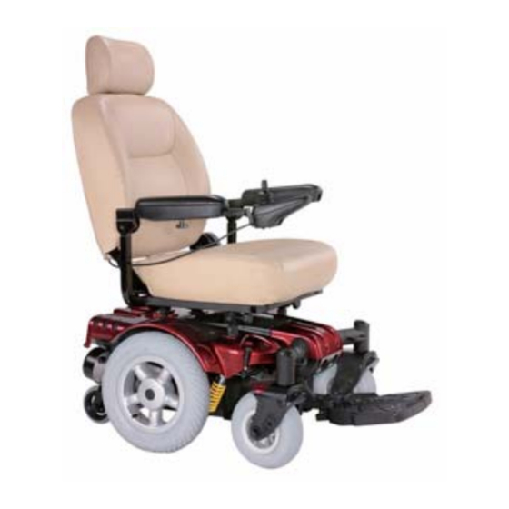
- Page 1 Sunfire Gladiator SG-3CRD-853 Drive Medical Design & Manufacturing 99 Seaview Boulevard Port Washington, NY 1105 Phone: 877-224-0946 Fax: 516-9984601 www.drivemedical.com...
- Page 2 COMPONENTS Your power wheelchair is shipped partially disassembled for protection during shipping. After unpacking, please check whether you have r eceived the following main components as our standard specification (See Fig.1 Mainframe with motor 4. Armrest (right) 2. Seat 5. Armrest (left) 3.
-
Page 3: Safety Instruction
10 degrees (slopes about 1/6). Also check that ramp surface is roughened to prevent slipping. Never drive across a slope or turn sharply on a slope. 9. When driving up curbs, always check the height of the curb to ensure that it does not exceed 1-1/2”(40mm) height. -
Page 4: U Se While Under The Influence Of Medication Or Alcohol
→ Flip up footplate or remove footrests → Turn both caster wheels towards the transfer direction to improve power chair stability during transfer. 11. When reaching, bending or leaning while seated on your power chair, make sure that you maintain a stable center of gravity to keep the power chair from tipping. General 12. - Page 5 States Food and drug Administration (FDA) suggests that the following statement be incorporated to the user’s manual for all power wheelchairs. Power wheelchairs and motorized scooters (in this section, both will be referred to as powered wheelchairs) may as susceptible to electromagnetic interference (EMI), which is interfering electromagnetic energy emitted from sources such as radio stations, TV stations amateur radio (HAN) transmitter, two-way radios and cellular phones.
-
Page 6: Environmental Conditions
of EMI. The higher the immunity level, the greater the protection. Your powered wheelchair has an immunity level of 20 V/m which should protect against comm sources of EMI. ENVIRONMENTAL CONDITIONS vironmental conditions may affect the safety and perfo rmance of your power wheelchair. - Page 7 ASSEMBLY INSTRUCTION 1. Installing the Seat (#2) Front Connection Connection point Point (Fig 2) (Fig 3) Slide the seat (#2) i nto the Connection points (both sides) in the Main fr ame (#1)(See ig2), put down the seat and connect the front connection point and make sure that tighten the tension knob in the front connection point.
- Page 8 Tension knob Armrest Frame (Fig 4) (Fig 5)
- Page 9 3. Installing controller and connect cables Assemble the controller (#3) on right armrest (#6) bracket with 2 screws.(See Fig 6)There is one plug (4 pins) in the other end on the controller. Please connect the 4 p plug with mainframe (#1) and make sure they are tightly connected.(See Fig 7) 4 pins (Fig 6) (Fig 7)
-
Page 10: Adjustments For Seating Confort
ADJUSTMENTS FOR SEATING CONFORT To maximize seating comfort, your power wheelchair lets you adjust: →Armrest width →Controller position →Backrest angle →Headrest height A. Armrest Width Adjustment → Loosen the tension knob → slide the armrest frame to your desired width →... -
Page 11: Backrest Angle Adjustment
T-Knob (Fig 10) C. Backrest Angle Adjustment Lift up the lever located the left side of the seat and adjust the backrest position to y desired angle.(See Fig 11) Seat Lever (Fig 11) Note: There are 5 different angles range when you slightly adjust the backrest to fit yours comfortable seating from the 105°... -
Page 12: Operation
Press this Button (Fig 12) OPERATION The power wheelchair is simple to operate. However, we recommend that you read carefully the following instructions to become familiarized with your new vehicle. Caution: Before you turn the power on, always be aware of the environment that surrounds you to select your desired speed. - Page 13 Battery ON/OFF Condition LED HORN Speed indication Speed control Speed control Joystick (Fig 13) A. Driving: 1. Controller ON/OFF Switch Press the ON/OFF button (I/O) switch located in front of the joystick to activate your power wheelchair. The battery condition meter will light up to indicate the current charge of your battery.
-
Page 14: Controller Display
engaging the joystick. This is a safety feature to prevent sudden start. →Gentle operation of the joystick will result in smoother transitions in speed a direction, while sharp operation of the joystick will result in drastic trans itions in direction and velocity. →When the wheelchair is in operation, the surface of the charger will become slightly hot. - Page 15 vehicle is not in use or when the power is OFF, they also have a manual feature th allows them to “free-wheel”. Free-wheeling is accomplished by turning the free-wheeling levers to the freewheeling position.(See Fig 14) Warning ! →Never free-wheel your power wheelchair on a slope. →Never free-wheel the motors while operating your vehicle.
-
Page 16: Thermal Protection
position. Note: Please refer to the section titled to check brakes in the Maintenance & Repair section to make sure brakes are in good condition. E. Thermal Protection: Your power wheelchair controller is equipped with a safety system called thermal rollback. -
Page 17: Batteries And Charger
BATTERIES & CHARGER BATTERY We recommend that you use deep-cycle batteries that are sealed and maintenance free for your power wheelchair. Both sealed lead-acid (SLA) and gel cell are deep-cycle batteries and are similar in performance. Deep-cycle batteries are specifically designed to provide power, drain down, and then accept a relatively quick recharge. - Page 18 →Plug the charger power cord (Round head) into the controller →Plug the charger power cord into a standard wall outlet. A red and a yellow (if battery charge is low) LEDs will illuminate. →When charging is completed, the yellow LED will turn green. →Disconnect the charger power cord from the wall outlet when the batteries are fully charged.
-
Page 19: Maintenance And Repair
fully charged in 4-10 hours. This will be indicated when the status light in the battery charger side panel turns green. Charging the battery longer than n ecessary will not harm the battery. We recommend that you charge the batteries for 8 to 10 hours after daily use. -
Page 20: Semi-Annual Checks
→Turn on the controller and turn down the speed and response adjustment knob. →After one second, check that the battery condition meter remains on condition. →Slowly push the joystick forward until you hear the parking brakes click. Immediately release the joystick. You must be able to hear each parking brake operates within a few seconds of joystick release. - Page 21 Keep wheels free from lint, hair, sand and carpet fibers. 3. Visually inspect the tire tread. If less than 1/32”, please h ave your tires replaced by your local dealer. All upholstery can be washed with warm water and mild soap. Occasionally check the seat and back for sagging, cuts, tears and replace if necessary.
-
Page 22: Diagnosis And Solution
FLASHING LIGHTS DIAGNOSIS AND SOLUTION The battery needs charging or there is a bad connection to the battery. Check the connections to the battery. If the connect- ions are good, try charging the battery. The left motor has a bad connection. Check the left motor connection. - Page 23 The following symptoms could indicate serious problems with your power wheel- chair. Contact your local dealer if any of the following arises: 1. Motor noise 2. Frayed harnesses 3. Cracked or broken connectors 4. Uneven wear on any of tires 5.
-
Page 24: Warranty
WARRANTY Your Drive brand product is warranted to be free of defects in materials and workmanship as follows: Chair/Scooter frame: Lifetime Electronic Controller and drive train components: 1 year Batteries: 6 months from time of installation This device was built to exacting standards and carefully inspected prior to shipment. This Lifetime Limited Warranty is an expression of our confidence in the materials and workmanship of our products and our assurance to the consumer of years of dependable service. - Page 25 DRIVE AUTHORIZED SERVICE AGENT NAME ADDRESS TELEPHONE EMAIL...
-
Page 26: Warranty Registration
Warranty Registration Please type or print. Serial # _______________________________________ Date Purchased ____/____/____ Owner Name ____________________________________________________________ Address _________________________________________________________________ City ____________________________________ State ________ Zip ________ Additional Required Owner Information Please indicate your understanding of your scooter by completing the following information. ________ I have read and fully understand _______ Owner’s Manual, especially sections on operating instructions, safety guidelines, maintenance and battery instructions. - Page 27 WARRANTY APPLICATION FORM Name 口 Male 口 Female Date of Birth Year Month Address 口 SUNFIRE GLADIATOR Model VIN: Motor Serial No: Key # Date of Purchase Year Month Purchaser Signature 10.1 VIN (VEHICLE INDIFICATION NUMBER) To ensure the correct after sales service and warranty...
Need help?
Do you have a question about the Sunfire Gladiator and is the answer not in the manual?
Questions and answers