Table of Contents
Advertisement
Quick Links
Advertisement
Table of Contents

Related Manuals for BridgeComSystems ComLink BRC-40U


Summary of Contents for BridgeComSystems ComLink BRC-40U
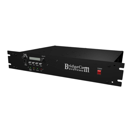
- Page 1 ComLink BRC-40U/50V Owner’s Manual By BridgeCom Systems, Inc.
- Page 2 Printed in the United States of America. LTR is a registered trademark of EF Johnson Corporation Windows is a registered trademark of Microsoft Corporation For Technical Support, please contact: BridgeCom Systems, Inc. 102 NE State Route 92 Highway, Suite C Smithville, MO 64089 Tel: (816)-532-8451 techsupport@BridgeComSystems.com...
-
Page 3: Table Of Contents
TABLE OF CONTENTS CHAPTER 1: INTRODUCTION .................... 5 ........................5 ELCOME CHAPTER 2: SPECIFICATIONS ..................6 CHAPTER 3: INSTALLATION ..................... 7 ........................7 NSTALLATION ........................7 OWER CHAPTER 4: OPERATION ....................8 ......................8 PERATING ODES ....................8 HANNEL AND ATABASE CHAPTER 5: REPEATER MODE................... - Page 4 CTCSS T ........................ 24 ONES DCS C ........................24 ODES APPENDIX D: REPEATER SYSTEM RECORD SHEET ............25 WARRANTY AND SERVICE ....................26 FCC STATEMENTS ......................27...
-
Page 5: Chapter 1: Introduction
CHAPTER 1: INTRODUCTION Welcome Thank you for purchasing the ComLink BCR REPEATER FM Repeater System. As part of the ComLink series, the BCR REPEATER has been developed to provide many of the features you, the communications user, have requested. The BCR REPEATER gives you a feature rich scalable repeater platform to grow as your system needs grow. -
Page 6: Chapter 2: Specifications
This Owner’s Manual will acquaint you with the features and specifications of the BCR-40U/50V. Every effort has been made in the preparation of this manual to ensure the accuracy of its contents. However, please note that one of the many features of the BCR-40U/50V includes upgradable firmware. -
Page 7: Chapter 3: Installation
CHAPTER 3: INSTALLATION Upon opening the shipping carton, the following items should be present and undamaged: • BCR FM Repeater System (UHF or VHF Version) • Detachable AC-line cord • One strip of four rubber feet The BCR repeater is capable of producing HIGH-powered RF signals that require proper termination into a suitable load. -
Page 8: Chapter 4: Operation
CHAPTER 4: OPERATION Operating Modes The BCR Repeater has four different modes of operation: repeater mode, base station mode, and auxiliary(AUX) mode. By default, the unit operates in repeater mode unless you explicitly change modes. This chapter will give you a brief overview of each of the modes. The individual modes are covered in detail in the chapters that follow. -
Page 9: Chapter 5: Repeater Mode
CHAPTER 5: REPEATER MODE Overview In repeater mode, each of the BCR Repeater’s 16 channels is capable of supporting 24 individual users. Each user may have one of 38 possible CTCSS tones or one of 83 possible DCS codes as well as inversions. While in repeater mode, the unit can be placed in remote programming mode. -
Page 10: User Settings
Remote Access Code: The System Operator can remotely manage the BCR Repeater by using DTMF tone sequences. The Remote Access Code is a four-digit number that you specify on a per channel basis. Before making any modifications, the System Operator must enter the Remote Access Code to gain access to the system. -
Page 11: Chapter 6: Base Station Mode
CHAPTER 6: BASE STATION MODE Overview In addition to its repeater features, the BCR repeater can be operated as a base station. While in base station mode, the system operator is able to communicate with any user on the selected channel. Operation To switch from repeater mode to base station mode, simply press and release the BASE button on the front panel. -
Page 12: Chapter 8: Alignment
CHAPTER 8: ALIGNMENT Overview The BCR Repeater is designed to operate in a wide range of the RF spectrum and the repeater is factory aligned to work at any frequency within that spectrum. However, because the repeater operates on a single transmit frequency at a time, you will likely want to optimize performance for that frequency. - Page 13 Adjust the RF POWER parameter Make sure the TX output is connected to a 50 ohm load. Rotate the SELECT knob to the RF POWER parameter in the alignment menu. Press-and-release the SELECT knob to engage the RF power amp. Using the service monitor, observe the output power level. Rotate the SELECT knob until the desired RF power is achieved.
-
Page 14: Chapter 9: Remote Programming
CHAPTER 9: REMOTE PROGRAMMING Overview Many settings of the BCR Repeater can be remotely programmed using DTMF tone sequences. You can add and delete users, as well as modify all individual user settings, such as TX/RX squelch options and courtesy tones. -
Page 15: Accessing Remote Program Mode
Accessing remote program mode To access remote program mode, the System Operator must key the remote access PIN, followed by the pound (#) symbol. Not just any user can enter the PIN – the repeater must also detect the presence of the System Operator’s CTCSS tone / DCS code. - Page 16 ENTER REMOTE MODE: ACTIVATE USER: Field Digits Field Digits Remarks 1) Remote access PIN [N][N][N][N] 1) Command [0][3] 2) User Slot [N][N] 00 < NN < 23 • The remote access PIN is preprogrammed on a per channel basis. You must know it •...
- Page 17 MODIFY USER RX DCS SIGNAL POLARITY: MODIFY CHANNEL ID INTERVAL: Field Digits Remarks Field Digits Remarks 1) Command [0][8] 1) Command [1][2] 2) User Slot [N][N] 00 < NN < 23 2) Interval (minutes) [N][N][N] 000 < NNN < 999 3) Polarity 0 = inverted 1 = non-inverted...
-
Page 18: Example 1: Add A New User And Modify The User
REBOOT: • You don’t need to be in remote programming mode to issue the reboot command. It can be used at any time. Field Digits Also, valid signaling is not required to issue 1) Command [5][5][5][5] a remote reboot command. •... - Page 19 3) Turn on tone-in-tail in the user’s newly created profile To turn on a user’s tone-in-tail, we need to enter the MODIFY USER TONE IN TAIL command prefix, the user’s slot number, and the tone-in-tail preference. The MODIFY USER TONE IN TAIL prefix is 10. We are modifying the user in Slot #3.
-
Page 20: Example 2: Deactivate An Existing User
Example 2: Deactivate an existing user In this example, we will deactivate an existing user. 1) Enter remote programming mode With the repeater turned on and in an idle state, the System Operator should push-to-talk, enter the remote access PIN, press the ‘#’ key, and then release the PTT button. The repeater should respond with the “remote mode entered”... -
Page 21: Chapter 11 Battery Backup/External Dc In
Chapter 11 Battery Backup/External DC In OVERVIEW The BCR REPEATER can be battery backed-up by connecting a 12 Volt deep cycle battery to the battery backup/Ext DC In terminals. If the AC Line fails, the internal relay will switch to where the battery can power the unit. -
Page 22: Appendix A: Accessory Connector Description
APPENDIX A: ACCESSORY CONNECTOR DESCRIPTION PIN # Description 13.8 Volts out (1A max) BASE STATION AUDIO OUT Gated Discriminator Audio Out RX Discriminator Out – Demodulated received audio RX MODULE - General Purpose Input RSSI – Received Signal Strength Indicator RX MODULE –... -
Page 23: Appendix B: Remote Programming Quick Reference
APPENDIX B: REMOTE PROGRAMMING QUICK REFERENCE Each command below must be followed the ‘#’ symbol to execute. After you press ‘#’ and dekey, you’ll hear either a success alert (four 1500 Hz tones) or a failure alert (four 500 Hz tones.) When you save and exit, you’ll hear a series of tones then three 600 Hz tones to let you know it exited remote programming. -
Page 24: Appendix C: Ctcss Tone/Dcs Code Tables
APPENDIX C: CTCSS TONE/DCS CODE TABLES CTCSS Tones Index Tone Index Tone Index Tone Index Tone Index Tone 67.0 91.5 118.8 156.7 210.7 71.9 94.8 123.0 162.2 218.1 74.4 97.4 127.3 167.9 225.7 77.0 100.0 131.8 173.8 233.6 79.7 103.5 136.5 179.9 241.8... -
Page 25: Appendix D: Repeater System Record Sheet
APPENDIX D: REPEATER SYSTEM RECORD SHEET NAME: RX Freq: TX Freq: Spacing: Power: Broadcast ID: Interval (mins): Rate (WPM): Remote PIN: Stuck Mic Timeout (secs): Slot User ID RX Option TX Option Courtesy Hold Time Tone In Tail... -
Page 26: Warranty And Service
Equipment returned for repair must have a return merchandise authorization (RMA) number. To obtain an RMA contact our Technical Support Department at (816)-532-8451 or email techsupport@BridgeComSystems.com. All returned equipment must have the RMA number listed on the outside of the shipping container. -
Page 27: Fcc Statements
FCC Statements Warning and Compliance Statement: Note: The ComLink BCR REPEATERV and BCR REPEATERU has been tested and found to comply with the limits for a Class B digital device, pursuant to part 15 of the FCC Rules. These limits are designed to provide reasonable protection against harmful interference in a residential installation.
Need help?
Do you have a question about the ComLink BRC-40U and is the answer not in the manual?
Questions and answers