Table of Contents
Advertisement
Advertisement
Table of Contents

Related Manuals for BridgeComSystems ComLink CS-540


Summary of Contents for BridgeComSystems ComLink CS-540
- Page 1 ComLink CS-540 Owner’s Manual Version 1.5, November 2006...
- Page 2 Printed in the United States of America. LTR is a registered trademark of EF Johnson Corporation Windows is a registered trademark of Microsoft Corporation For Technical Support, please contact: BridgeCom Systems, Inc. 617 Liberty Road Smithville, MO 64089 Tel: (816)-532-8451 techsupport@BridgeComSystems.com...
-
Page 3: Table Of Contents
TABLE OF CONTENTS CHAPTER 1: INTRODUCTION .................... 5 ........................5 ELCOME CHAPTER 2: SPECIFICATIONS ..................6 ....................7 RONT ANEL ESCRIPTION ..................... 7 ANEL ESCRIPTION CHAPTER 3: INSTALLATION ..................... 8 ........................8 NSTALLATION ........................8 OWER CHAPTER 4: OPERATION ....................9 ...................... - Page 4 CHAPTER 12: BATTERY BACKUP/EXTERNAL DC IN ............24 APPENDIX A: ACCESSORY CONNECTOR DESCRIPTION ........... 25 APPENDIX B: REMOTE PROGRAMMING QUICK REFERENCE ..........26 APPENDIX C: TONE/CODE TABLES ................. 27 CTCSS T ........................ 27 ONES DCS C ........................27 ODES APPENDIX D: REPEATER SYSTEM RECORD SHEET ............28 APPENDIX E: 120V AC ~ 240V AC CONVERSION ............
-
Page 5: Chapter 1: Introduction
Welcome Thank you for purchasing the ComLink CS-540 FM Repeater System. As part of the ComLink series, the CS-540 has been developed to provide many of the features you, the communications user, have requested. The CS-540 gives you a feature rich scalable repeater platform to grow as your system needs grow. -
Page 6: Chapter 2: Specifications
CHAPTER 2: SPECIFICATIONS General CS-540U CS-540V Number of Channels: Operating Voltage: 11 V DC Min / 13.8 V DC Nominal / 15 V DC Max Channel Spacing: 5kHz/6.25KHz/Splinter Current Drain: 12A Max Weight: 18.5 lbs. Weight w/ duplexer: 19.5 lbs. Frequency Range: 450-480 MHz 148-174 MHz... -
Page 7: Front Panel Description
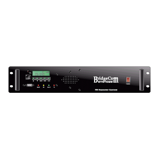
Front Panel Description 1) Microphone input jack 2) Volume control knob 3) Alphanumeric and Icon LCD 4) 5 button keypad (▲,▼, BASE, MON, AUX) 5) Computer port DB9 Female 6) LED status indicators (BASE, RX, VALID, TX) 7) Internal Speaker 8) Lighted power switch Rear Panel Description 1) Fan... -
Page 8: Chapter 3: Installation
CHAPTER 3: INSTALLATION Upon opening the shipping carton, the following items should be present and undamaged: • CS-540 FM Repeater System • This CS-540 Owner’s Manual • Detachable AC-line cord • One strip of four rubber feet The CS-540 is capable of producing HIGH-powered RF signals that require proper termination into a suitable load. -
Page 9: Chapter 4: Operation
CHAPTER 4: OPERATION Operating Modes The CS-540 has three different modes of operation: repeater mode, base station mode, and auxiliary mode. By default, it operates in repeater mode unless you explicitly change modes. This chapter will give you a brief overview of each of the modes. The individual modes are covered in detail in the chapters that follow. Also in each of the various operating modes an external peripheral can be connected to the accessory connector located on the rear of the unit. -
Page 10: Chapter 5: Repeater Mode
CHAPTER 5: REPEATER MODE Overview In repeater mode, each of the CS-540’s 16 channels is capable of supporting 64 individual users. Each subscriber may have one of 50 possible CTCSS tones or one of 112 possible DCS codes. While in repeater mode, the CS-540 can be placed in remote programming mode and the selected channel’s properties and user database can be changed using transmitted DTMF tone command sequences. -
Page 11: User Settings
COS Enable: By enabling the COS output feature (Pin 17 “Inactive”, their calls will not repeated, although all their of the Accessory Connector) you can customize how COS information will still be retained in the system. This output will operate. The COS output can be made to option is useful if you want to suspend the repeater toggle when carrier is present on the receiver or when... -
Page 12: Chapter 6: Base Station Mode
CHAPTER 6: BASE STATION MODE Overview In addition to its repeater features, the CS-540 can also be operated as a base station. While in base station mode, the system operator can communicate with any user on the selected channel. Operation To switch from repeater mode to base station mode, simply press and release the button on the front panel labeled BASE. -
Page 13: Chapter 7: Auxiliary Mode
CHAPTER 7: AUXILIARY MODE Overview By entering auxiliary (AUX) mode, the repeater's internal controller is disabled and the CS-540 may be controlled by an external peripheral. In addition, while in AUX mode, you can adjust the display illumination level, enable/disable the TX power amplifier, enable/disable the front panel speaker, enable/disable the internal LTR Decoder. -
Page 14: Chapter 8: Remote Programming
CHAPTER 8: REMOTE PROGRAMMING Overview Many settings of the CS-540 can be remotely programmed using DTMF tone sequences. You can add and delete users, as well as modify all individual user settings, such as TX/RX squelch options and courtesy tones. In addition, many channel settings can be modified remotely as well, such as the broadcast ID interval and the TX Timeout timer. -
Page 15: Accessing Remote Program Mode
Accessing remote program mode To access remote program mode, the System Operator must key the remote access PIN, followed by the pound (#) symbol. Not just any user can enter the PIN – the repeater must also detect the presence of the System Operator’s CTCSS tone / DCS code. - Page 16 ENTER REMOTE MODE: ACTIVATE USER: Field Digits Remarks Field Digits 1) Command [0][3] 1) Remote access PIN [N][N][N][N] 2) User Slot [N][N] 00 < NN < 63 • The remote access PIN is preprogrammed • All users are active by default. This on a per channel basis.
- Page 17 MODIFY USER RX DCS SIGNAL POLARITY: MODIFY CHANNEL ID INTERVAL: Field Digits Remarks Field Digits Remarks 1) Command [0][8] 1) Command [1][2] 2) User Slot [N][N] 00 < NN < 63 2) Interval (minutes) [N][N][N] 000 < NNN < 999 3) Polarity 0 = inverted 1 = non-inverted...
-
Page 18: Example 1: Add A New User And Modify The User
EXIT WITHOUT SAVE: REBOOT: Field Digits Field Digits 1) Command [9][8] 1) Command [5][5][5][5] • Upon exit, the repeater will transmit the • This command remotely reboots the CS- exit remote mode alert, which is three 540 as if someone had manually toggled consecutive 600 Hz tones. - Page 19 In order to add a user, we need to enter the following sequence (without the dashes): [0][1]-[3][0]-[0][9][4]-[#] Upon dekey, the repeater should respond with a success alert, which is a series of four 1500Hz tones. If it failed, you’ll hear a failure alert, which is a series of four 500Hz tones. If this process fails, then possible causes for this failure include: Slot #30 is already occupied, DCS code 223 is already being used by another user, or the command was entered incorrectly.
-
Page 20: Example 2: Deactivate An Existing User
Example 2: Deactivate an existing user In this example, we will deactivate an existing user. 1) Enter remote programming mode With the repeater turned on and in an idle state, the System Operator should push-to-talk, enter the remote access PIN, press the ‘#’ key, and then release the PTT button. The repeater should respond with the “remote mode entered”... -
Page 21: Chapter 9: Alignment
CHAPTER 9: ALIGNMENT Overview The CS-540 is designed to operate in a wide range of the RF spectrum and the repeater is factory aligned to work at any frequency within that spectrum. However, because the repeater operates on a single transmit frequency at a time, you will likely want to optimize performance for that frequency. -
Page 22: Fine-Tuning Transmitter Alignment
It should be noted the receiver is already factory aligned to open squelch at 12dB SINAD and close at 8dB SINAD. Fine-tuning Transmitter Alignment In order to fine-tune the transmitter alignment, you’ll need to find the optimal value of each of the six parameters listed on the previous page. -
Page 23: Chapter 10: Keypad Lock
CHAPTER 10: Keypad Lock Overview Many of the operations such as alignment and channel change are carried out using the front panel’s keypad, therefore the CS-540 incorporates a simple keypad lock to prevent unwanted manipulation of the CS-540’s settings during operation at the site. The keypad can be locked and unlocked in any one of the three operating modes. -
Page 24: Chapter 12: Battery Backup/External Dc In
Figure 11-1: Duplexer Installation – UHF Version Shown Chapter 12: Battery Backup/External DC In OVERVIEW The CS-540 can be battery backed-up by connecting a 12 Volt deep cycle battery to the battery backup/Ext DC In terminals. If the AC Line fails, the internal relay will switch to where the battery can power the unit. -
Page 25: Appendix A: Accessory Connector Description
APPENDIX A: ACCESSORY CONNECTOR DESCRIPTION PIN # Description 13.8 Volts out (1A max) Communications Bus – BUSY Communications Bus – DATA Discriminator Out – Demodulated received audio RSSI – Received Signal Strength Indicator CrossBand Discriminator Out – X-Band Repeater Rx Module – General Purpose Input 1 Rx Module –... -
Page 26: Appendix B: Remote Programming Quick Reference
APPENDIX B: REMOTE PROGRAMMING QUICK REFERENCE Each command below must be followed the ‘#’ symbol to execute. After you press ‘#’ and dekey, you’ll hear either a success alert (four 1500 Hz tones) or a failure alert (four 500 Hz tones.) When you save and exit, you’ll hear a series of tones then three 600 Hz tones to let you know it exited remote programming. -
Page 27: Appendix C: Tone/Code Tables
APPENDIX C: TONE/CODE TABLES CTCSS Tones Index Tone Index Tone Index Tone Index Tone Index Tone 254.1 199.5 167.9 127.3 91.5 250.3 196.6 165.5 123.0 88.5 241.8 192.8 162.2 118.8 85.4 233.6 189.9 159.8 114.8 82.5 229.1 186.2 156.7 110.9 79.7 225.7 183.5... -
Page 28: Appendix D: Repeater System Record Sheet
APPENDIX D: REPEATER SYSTEM RECORD SHEET NAME: RX Freq: TX Freq: Spacing: Power: Broadcast ID: Interval (mins): Rate (WPM): Remote PIN: Stuck Mic Timeout (secs): Slot User ID RX Option TX Option Courtesy Hold Time Tone In Tail... - Page 29 Slot User ID RX Option TX Option Courtesy Hold Time Tone In Tail...
-
Page 30: Appendix E: 120V Ac ~ 240V Ac Conversion
Appendix E: 120V AC ~ 240V AC Conversion It is recommended the following service be performed by a qualified service technician. To convert the CS-540 to 240V AC, follow these steps: 1. Make sure the unit is unplugged from the AC outlet. 2. -
Page 31: Appendix G: Lcd Quick Reference Sheet
APPENDIX G: LCD Quick Reference Sheet The following is a quick description of what all the icons on the display mean and how to change their settings. Left Arrow – This arrow indicates the composite input to the transmitter is enabled. The composite input allows for DC coupled broadband audio to be transmitted. -
Page 32: Warranty And Service
Equipment returned for repair must have a return merchandise authorization (RMA) number. To obtain an RMA contact our Technical Support Department at (816)-532-8451 or email techsupport@BridgeComSystems.com. All returned equipment must have the RMA number listed on the outside of the shipping container. -
Page 33: Fcc Statements
FCC Statements Warning and Compliance Statement: Note: The ComLink CS-540V and CS-540U has been tested and found to comply with the limits for a Class B digital device, pursuant to part 15 of the FCC Rules. These limits are designed to provide reasonable protection against harmful interference in a residential installation.
Need help?
Do you have a question about the ComLink CS-540 and is the answer not in the manual?
Questions and answers