Page 1
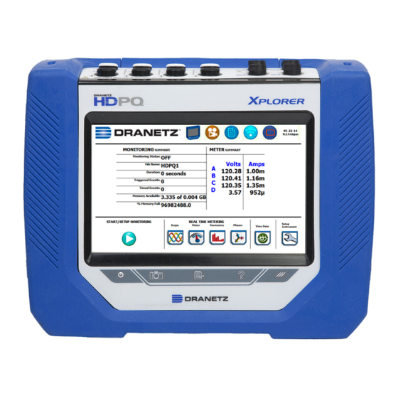
Quick Reference Guide For the Dranetz HDPQ Xplorer / Xplorer 400 / Guide / Visa product family. It is recommended that the user still be familiar with the complete User Guides for the respective products, as it contains more detailed information about all of the functions, as well as the specifications and accessories.
Page 2
No part of this book may be reproduced, stored in a retrieval system, or transcribed in any form or by any means—electronic, mechanical, photocopying, recording, or otherwise—without prior written permission from the publisher, Dranetz, Edison, NJ 08818-4019. Printed in the United States of America. P/N QR-HDPQ Rev B 06.16.14...
Page 3
ADVERTENCIA Una conexión incorrecta de este instrumento puede producir la muerte, lesiones graves y riesgo de incendio. Lea y entienda este manual antes de conectar. Observe todas las instrucciones de instalación y operación durante el uso de este instrumento. La conexión de este instrumento a un sistema eléctrico se debe realizar en conformidad con el Código Eléctrico Nacional (ANSI/NFPA 70-2014) de los E.E.U.U., además de cualquier otra norma de seguridad correspondiente a su establecimiento.
WARNUNG Der falsche Anschluß dieses Gerätes kann Tod, schwere Verletzungen oder Feuer verursachen. Bevor Sie dieses Instrument anschließen, müssen Sie die Anleitung lesen und verstanden haben. Bei der Verwendung dieses Instruments müssen alle Installation- und Betriebsanweisungen beachtet werden. Der Anschluß dieses Instruments muß in Übereinstimmung mit den nationalen Bestimmungen für Elektrizität (ANSI/NFPA 70-2014) der Vereinigten Staaten, sowie allen weiteren, in Ihrem Fall anwendbaren Sicherheitsbestimmungen, vorgenommen werden.
Caution, refer to accompanying documents (this manual). Alternating current (AC) operation of the terminal or device. Direct current (DC) operation of the terminal or device. Power switch Safety Precautions The following safety precautions must be followed whenever any type of voltage or current connection is being made to the instrument.
The Xplorer is designed to meet both the IEEE 1159 and IEC 61000-4- 30 Class A standards for accuracy and measurement requirements. It can do PQ-optimized acquisition of power quality related disturbances and events.
Zone drop down selection list. NOTE: Time and/or date cannot be changed if monitoring is on. The Xplorer also lets you synchronize time, so that all of your devices are using the same time for data recording. Time sync options include GPS, NTP or Real Time Clock (RTC). Each Time Sync Source button toggles the respective source enabled or disabled.
Connecting to AC Power Source Power The Xplorer AC adapter can be connected to a 50/60 Specifications Hz, 90-264V AC power input source. CAUTION Always set the power switch to the off position before connecting or disconnecting the input power cable.
Page 11
AC Power The Xplorer can be operated from a 50/60 Hz, Source 120/240V AC power source with or without the battery pack installed. • Voltage range, 120/240V AC • Frequency, 50/60 Hz • Power consumption, 20W STEP 1 Connect the AC adapter/battery charger plug into the left side of the instrument.
Voltage and Current Connections - There are four differential voltage and four differential current channels, which can be wired to measure a variety of circuit configurations. Use only Dranetz voltage leads and current probes for proper operation. Do not exceed the marked maximum ratings.
Left Side View Left Side Panel - contains the power switch, GPS receiver port, and AC adapter input connector. Right Side View Right Side Panel - contains the ethernet port and two USB port connectors for the USB flash drive, as well as the USB cable for plug & play file transfer directly to a computer.
If the battery pack is in need of replacement, de-energize the connections and power to the instrument before opening the battery door. Replace the pack only with the Dranetz battery pack P/N BP-HDPQ.
MAKING CONNECTIONS WARNING Death, serious injury, or fire hazard could result from improper connection of this instrument. Read and understand the warnings in the beginning of this manual before connecting this instrument. ADVERTENCIA Una conexión incorrecta de este instrumento puede producir la muerte, lesiones graves y riesgo de incendio.
There are two optional fuse voltage adapter accessory Voltage Adapter kits available for use with the measurement cables for the HDPQ Xplorer. A single kit (P/N FVA-1K1) contains one (1) fuse voltage adapter and one (1) black measurement connecting cable 50 cm in length.
Page 17
The single fuse voltage adapter kit is used for one single voltage measurement input, while the four fuse voltage adapter kit is used for a three phase and neutral voltage measurement inputs. Wire Markers Each kit consisting of snap-on wire markers in various colors is supplied as described in the following table.
Page 18
WARNING: Do not replace fuse again if failure is repeated. Repeated failure indicates a defective condition that will not clear with replacement of the fuse. Refer condition to a qualified technician. --------------------------------------------------------------------------------- The Xplorer can monitor the following power configurations: Single Phase Split Phase ...
3 Phase, Four Wire Wye Channels A, B, and C are connected to voltage and current probes. The neutral is connected to common, and is the reference for the three channels. The figure also shows voltage connection using channel D as a differential input for measuring neutral to ground voltage.
3 Phase (Floating or Grounded) Delta In this power connection, the Xplorer uses voltage channels A, B, and C as differential inputs with channel A using source voltage A-B, channel B using B-C, and channel C using C-A as the reference. Current probes are connected to channels A, B, and C.
XPLORER UI TOUCHSCREEN FEATURES All Dranetz HDPQ Xplorer screen functions are operable using the color LCD touch screen display. Use your finger and/or a stylus to apply light pressure to the LCD screen to initiate touch screen recognition. The touch screen display is also workable with lineman gloves on. In order to reduce power consumption, the backlight of the LCD screen times-out after a specified programmable time of no user activity.
XPLORER TOUCH ICON BUTTONS Touch Icon Buttons There are three touch icon buttons located below the LCD screen - Snapshot, Mini-Report Capture and Help. The buttons allow you to perform functions specific to the screen on display, as described below: Snapshot Icon Button This button takes a snap shot image of the current screen.
Monitoring Status - On or Off File Name - user specified or HDPQ Xplorer xx, where xx increments every time data is saved using the same file name Duration – length of time from the start of monitoring to the present time while monitoring is on ...
Setup is a configuration of parameter thresholds that control the data recorded by the Xplorer. See Section - Setup Monitoring. NOTE: The Start Monitoring icon changes into Stop Monitoring when monitoring status is on, and vice versa.
The auto- configured setup enables you to proceed directly with data monitoring. The Xplorer allows you to perform automatic setup for power quality or for energy/demand, depending on your application. Wizard Setup takes you through a series of screens prompting for information about the circuit to be monitored and the monitoring settings.
2 ½ Element without Vb 2 ½ Element without Vc While monitoring any of the above configurations, the Xplorer can also be connected to monitor neutral to ground voltage, and neutral or ground current. Automatic Setup for Power Quality Automatically configures the setup for monitoring quality of supply based on IEEE and IEC typical trigger settings.
Automatic Setup for Energy/Demand Automatically configures the setup for monitoring energy/demand. Automatic Setup is a one-stop process using pre-defined values to set the instrument automatically. You have the option to view the summary list of parameter settings, change probe types, and/or proceed directly with data monitoring.
Next. The Current Probes – Turns Ratios window is displayed. Circuit Type Selection The Xplorer is able to display wiring diagrams from which you can select the circuit type appropriate to your application. The instrument will automatically select and display the detected circuit type when entering the screen, and compare the detected voltages, currents, and phase sequence (if applicable) to the selected circuit type.
Page 29
An auto circuit detection window is displayed to select the detected circuit type, nominal voltage, current and frequency. Parameters that match expected measurements are displayed in green. Ones that do not match are displayed in red. Frequency, Voltage and Current Settings The Nominal Values screen allows you to select frequency sync options, including channel source (Va, Vd, Ia, Id), speed of response (Standard - Utility Power Line, Fast - Local Generator or Internal), and frequency...
Page 30
Monitoring Modes The Xplorer provides nine monitoring modes of operation from which to monitor and capture data relevant to the user’s application. Selecting any setup category automatically sets trigger and capture conditions. Advanced users are free to mix and match settings using the trigger limits discussed in the next section.
Page 31
The Xplorer is also designed to be left unattended in the field, recording statistically representative data for long-term analysis. Continuous Data Logging: This logs the rms and power values once per second for totally gapless logging.
Page 32
Trigger Limits for all Monitoring Modes Except Voltage Compliance (EN50160): The Xplorer allows you to set the limits for the following triggers: Set RMS Limits – use to review/modify limits for rms variation as well as set the amount of rms value (in cycles) to record before and after the trigger cycle.
Page 33
The Xplorer uses four different algorithms to detect and record transients, while Dranetz HDPQ Guide and Visa have three. You have the option to check Enable Automatic Limit Incrementing to set limit trigger channel settings to auto- threshold mode. ...
Page 34
Set High Frequency Transients – the high speed sampling analog board installed in Dranetz HDPQ Xplorer enables it to detect and capture transients as small as 1 microsecond in duration. This transient detection algorithm is only available on...
Page 35
Timed Intervals – use to define how often you want the Xplorer to save data periodically, regardless of power quality disturbances and journal limits. The intervals for timed readings are user programmable.
Page 36
Monitoring Mode for EN50160 Voltage Compliance The following screen appears if the selected monitoring mode is Voltage Compliance (EN50160): If the default settings for the specified monitoring mode are acceptable, proceed to the next tab Finalize (if there is nothing else to change). If Strict Compliance is not checked, you can customize the setting on this screen.
Page 37
Under the Stop monitoring options, select one from the following: Storage full - to end monitoring when memory storage is full Delay - use the window provided to enter the number of days, hours, minutes or seconds of delay to end monitoring ...
Exit Setup At the end of the Wizard Setup, the Exit Setup screen prompts you to either accept the setup changes or not, before going on to start monitoring (if accepted). You also have the option to use the instrument as a meter, where monitoring setup changes are retained without turning monitoring on.
Load Setup Template The Xplorer lists the setup template files (.set) stored in internal memory or external USB device, along with wiring configuration, setup mode application and location of file. Setup files are arranged in the order of date and time they were recorded.
Page 40
Archive to USB - copies and saves data files from internal memory to an external memory device (USB). Once the files have been saved, ® you will need the Dranetz Dran-View program to retrieve and view the files in your computer.
Change Instrument Configuration The Xplorer lets you manage the instrument to ensure that it runs efficiently, and the instrument is set up according to your preferences and application. View/Save Monitoring Setup summary displays the list of parameter settings for the present setup application.
INSTRUMENT SETTINGS Instrument settings describe the miscellaneous tasks that you can perform to keep the Xplorer running efficiently. These are tasks that you might perform only occasionally. You can configure the instrument to set up the following: Time and date display ...
Xplorer from any other computer or mobile device anywhere using the Internet. VNC software is cross-platform, allowing remote screen- sharing control of the Xplorer. A VNC app or program (not supplied by Dranetz) is required on your computer, tablet or smartphone for VNC remote control.
IP address of the instrument. 3) Enter the Username and Password for the instrument. The username is always admin. The default password is Dranetz. Password setups can be done in the instrument's Communications settings. 4) The web page will show four folders, each of which contains the following information to upload: screens –...
Download Data via USB Connection 1) Plug the small end of the USB active sync cable into the small USB connector on the right side of the HDPQ instrument. Plug the other end into the USB connector on your computer. ®...
REAL TIME METER MODES Scope Mode Scope mode functions as an oscilloscope, displaying real-time waveforms of voltage and current for up to eight channels simultaneously, updated approximately once every three seconds. The colors of waveform display are user programmable. Waveforms may be displayed on a single or dual axis (overlaid or stacked).
Distortion, Unbalance, Advanced Power, Advanced Demand & Energy and Advanced Flicker. The function keys at the bottom of the meter screens change depending on the parameter tab selected. NOTE: Meter mode operation does not interfere with any of other Xplorer monitoring or recording functions. Dashboard...
Harmonics Harmonics display the amplitude and phase of each harmonic to the 127th harmonic in both graphical and textual format. You can select which parameter to show the harmonics for (V,I,W), which channel (A,B,C,D) zoom in on the 5Hz components, set options such as show harmonics and/or interharmonics and then display in Hz or harmonic number, scale to the fundamental or absolute value, and list the harmonic magnitudes and phase angles in tabular fashion.
Strip Chart Recorder Strip Chart Recorder displays a real-time auto-scaled graph of selected parameters, updated once every 3 seconds. The initial strip chart screen records up to 10-minutes worth of horizontal scale data, with the vertical axis also initially on auto-scale. Once 10-minutes worth of data is drawn across the entire graph, the horizontal scale continues to shift forward in time with each update.
Trend, Event List, Event Plot, and Event Waveform are available for display, with options to view detailed information in graphic as well as textual form. The Xplorer also does Voltage (Quality of Supply or QOS) compliance monitoring as specified by EN50160, or other similar voltage compliance standards.
Trend Plot Users can generate time plots or trend visualizations for all journalled data combined with min/max/avg recordings of that parameter. Most journal parameters have multiple channels to plot. The Trend screen can display up to four (4) stacked graphs with as many as four (4) channels in each graph.
Event List Presents a summary of all captured events in the order in which they occurred. Each event entry contains the date and time when the event was captured, the color coded channel/parameter of the captured event, the event category and event classification. The event list can be filtered by type and/or time.
NOTE: Event plot displays events in rms by default. To view event plot in waveform display, press the Waveform icon on the taskbar. Event Waveform The Xplorer allows you to view events in graphic waveform display. Waveforms from transient event capture NOTE: The instrument will only display waveform data for channels that are enabled to record waveforms.
The event details will also include result of the Sag Directivity and Power Factor Correction Capacitor AnswerModules (not available on Dranetz HDPQ Visa). Each event entry is identified by the time and date when the event was captured (shown on header row), the trigger parameters, and characterization details pertaining to the selected event entry.
REPORTS You have the option to view and set up data via the Voltage Compliance Report, Energy/Demand Audit Report, Harmonics Statistics Report or the Mini-Report Viewer. Each report has their own method of presenting compliance data, as well as differs on the length of evaluation period to monitor compliance.
Page 56
You can view component graphs for three parameters using the soft keys provided - Frequency for Power Frequency graph, Harmonics for Harmonic graph, and Interharmonics for Interharmonic graph. DISDIP The EN50160 DISDIP (distribution of dips) table is based upon the event statistics calculated by EN50160.
Harmonic values up to order number 25. Energy and Demand Report The Xplorer gives you the option to view the demand and energy report. The report list, as shown below, helps you monitor and manage energy consumption including utility costs.
Harmonics Statistics Report Harmonics Statistics Report allows you to set up a harmonic statistics report, based on the 3-second data calculating the 95 and 99% values per IEC 61000-4-7 and IEEE 519. Use the function keys at the bottom of the screen – Open, Start Today, Start Date, Failed Only, Weekly Only - to set up the report.
User replaceable instrument batteries are warranted for a period of one year from the date of invoice. Certain Dranetz branded accessories, such as current transformers and other accessories not manufactured by...
Need help?
Do you have a question about the Xplorer and is the answer not in the manual?
Questions and answers